Get in touch with Blue Membrane Company

Brackish Water RO · Engineered Design
High-Recovery Brackish Water Reverse Osmosis Systems, Engineered Design & Z1 Membranes
Increase brackish water RO recovery to 75%, without giving up membrane life. Blue Membrane designs the array staging, concentrate management and anti-fouling Z1 elements enabling industrial, municipal and commercial facilities to achieve high recovery safely, at 1 to 500 TPD.
≤10,000
Feed TDS (mg/L)
50–75%
System Recovery
99.6%
Z1 Salt Rejection
1–500
Capacity (TPD)
≥98%
System Desalination
BW30
DuPont Drop-in Compatible
Why Brackish Water RO Recovery Stalls, the Scaling Ceiling
Most brackish water reverse osmosis units run into trouble far below the recovery rate the plant operator hoped for. It’s not the membrane it’s the chemistry. As feed water becomes more concentrated through a brackish water RO system, sparsely soluble salts reach their saturation point and precipitate out in the form of crystallization on the membrane.
And it’s the ceiling that the industry data has been stubbornly hovering over since. Recovery from brackish water is almost always less than 75% and rarely rises above 80% (and only then at lower feed TDS) [US9073763B2]. The site-specific real limit for any given application is its saturation index.
The recovery-limiting scale species (brackish feed):
- Calcium carbonate (calcite) – The earliest to precipitate at the point where concentrations and pH start to increase
- Calcium sulfate (gypsum) – saturates fast in sulfate-rich groundwater
- Barium & strontium sulfate (baryte, celestine) – trace ions, excessive scaling effects
- Silica – polymerized over ~200 mg/L, most difficult to redissolve [ACS EST]
And A RO system on brackish water does more than just filter your drinking water at the tap. It pushes feed water against a semipermeable membrane, removes the total dissolved solids and contaminants, and lowers the concentration to a level that’s potable. And it’s this exact filtration and water purification task that makes running in high-recovery mode chemically challenging – and unlike consumer water filters, it has to maintain the performance consistently at scale.
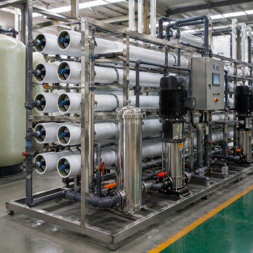
Without an design answer that breaks the ceiling at your desired recovery, you lose three points simultaneously: life on the membrane decreases, permeate salinity increases, and your pump has to work much harder for the same permeate rate. High recovery isn’t a slider you adjust, it’s a design system you implement, and that’s what we cover next.
At Blue Membrane, each brackish water RO train is designed off the feed’s saturation index, since that structural limitation, not the membrane rating, is exceeded first at 600 psi. A common mistake is trying to dial the recovery instead of design the system; unlike an inline water filter, that mistake will cost you membranes in an industrial train.
IMPLEMENT DESIGN SYSTEMHigh-Recovery BWRO Design: The 4 Levers
Here’s the counter-intuitive trick most spec sheets omit: higher recovery isn’t necessarily a good thing. Higher than safe recovery on your feed chemistry will be gained by trading scaling, salt passage and energy costs for water [US8617398B2].
ENGINEERING PHILOSOPHY
At Blue Membrane, we treat 75% as an engineering sweet spot, not a number to chase at all costs. Here are the four ways you design to get there reliably.
“
LEVER 01 | SYSTEM
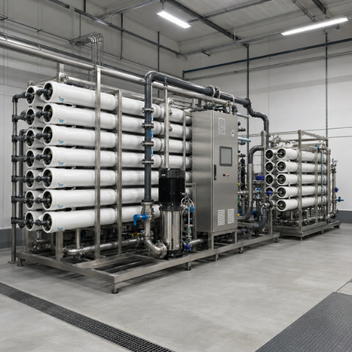
Lever 1, Array staging
In the second case, a 2-1 array is fed by the first-stage concentrate to a second, smaller stage array; the flow velocity is maintained at high levels as the volume decreases. Arrays designed for field operation with 2-1 staging and antiscalant routinely operate at 75 to 85% recovery, and 83% has been achieved.
LEVER 02 | PROCESS
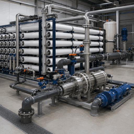
Lever 2, Concentrate & brine management
A recirculating, controlled slip stream of concentrate will help to keep the membrane surface clean and the build up of new crystal seeds postponed. Energy recovery devices will use back pressure from the reject stream to offset some of the pumping requirements – up to 30% energy reduction can be achieved at high recovery.
LEVER 03 | SPECIFICATIONS
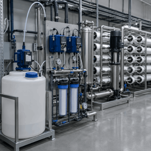
Lever 3, Anti-scaling pretreatment
As the system gets close to saturation levels and the water can no longer absorb more scale minerals, new scale crystals start forming on the surface of the membrane, this can lead to scaling and reduced performance and membrane life. Polyamide antiscalant dosed at 1-5 mg/L can delay the nucleation of calcite and gypsum and ensure the feed SDI is below membrane limit. This is how a 60% recovery is converted into a 75% design.
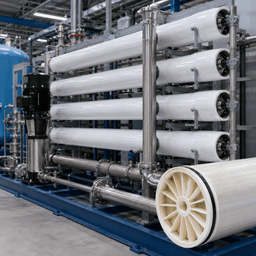
LEVER 04 | APPLICATIONS
Lever 4, Low-fouling membrane selection
Membrane choice itself sets the limit. Methods described in USPTO applications demonstrate that by reducing the scaling and fouling potential of a feed water, recovery can be governed by osmotic pressure, instead of by the potential for crystal formation [US6537456B2], and the ionization of silica with pH-shift can allow for increased rejection [US5925255A].
“We size brackish arrays to the scaling index of the actual feed, not to a marketing recovery number. On most groundwater we hold the design at 75% — the last five points of recovery cost more in membrane life than they return in water.”— Blue Membrane Engineering Team, Application Design
BWRO Recovery-Rate Design Ladder
Refer to the chart below to determine realistic design recovery based on the feed’s TDS and the most prevalent scale risk. It incorporates published saturation limits with Z1 element characteristics and each row should be considered a starting point for site-specific modeling rather than a promise of performance.
| Feed TDS (mg/L) | Dominant scale risk | Target recovery | Recommended array | Anti-scaling measure |
|---|---|---|---|---|
| 1,000 | Low (calcite) | 75–80% | 2-1 staging | Antiscalant 1–2 mg/L |
| 2,000 | Calcite | 75% | 2-1 staging | Antiscalant 2 mg/L + pH trim |
| 3,000 | Calcite + gypsum | 70–75% | 2-1 staging | Antiscalant 2–3 mg/L |
| 4,000 | Gypsum | 70% | 2-1 staging | Antiscalant 3 mg/L |
| 5,000 | Gypsum + silica | 65–70% | 2-1 / 3-2 staging | Antiscalant 3–4 mg/L |
| 6,000 | Silica | 65% | 3-2 staging | Antiscalant + silica dispersant |
| 8,000 | Silica + sulfate | 60–65% | 3-2 staging | Dispersant + pH control |
| 10,000 | High mixed scaling | 55–60% | 3-2 staging | Dispersant + concentrate recycle |
| >10,000 | Beyond BWRO band | SWRO / hybrid | Seawater array | Route to seawater design |
Blue Membrane Z1 Series, Elements Built for High-Recovery Operation
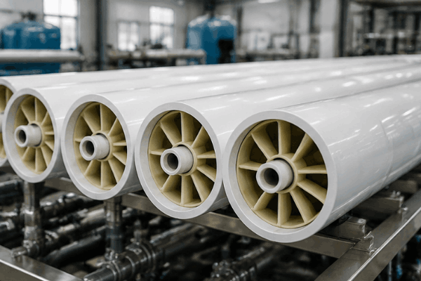
High recovery design fails on the wrong element. High recovery RO requires a high rejection, anti-fouling element. Z1 Series membrane uses a reduced-roughness, polyamide surface with engineered charge characteristics to inhibit scaling and organic adsorption.
Its wide, 34-mil feed spacer and short-leaf geometry reduce pressure drop and lengthen cleaning cycles-the two parameters determining whether a 75 percent design will hold over time. Each MB-Z1-8040 PLUS delivers up to 12,000 gallons per day (GPD) per element, and every model is dimensionally interchangeable with standard pressure vessel sizes.
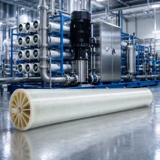
MB-Z1-8040
- 10,500 GPD (39.7 m³/d) · 400 ft² · 34 mil
- Stable rejection 99.6% · Compatible with DuPont BW30-400/34
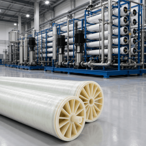
MB-Z1-8040 PLUS
- 12,000 GPD (45.4 m³/d) · 440 ft² · 28 mil
- Stable rejection 99.6% · Compatible with DuPont BW30HR-440
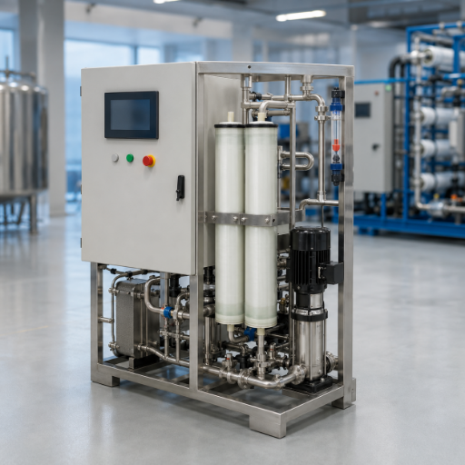
MB-Z1-4040
- 2,400 GPD (9.1 m³/d) · 85 ft² · 34 mil
- Stable rejection 99.6% · Pilot & compact skids
Drop-in DuPont FilmTec compatibility
If your high-recovery design is based on a DuPont FilmTec element, Z1 drops in as a direct replacement, the 4040 and 8040 elements are universal. That lets Z1 serve as a like-for-like alternative, with no system modification [ref].
Each Z1 brackish water membrane is manufactured in house to exacting standards for reliable, long term operation and 99.6% in-practice rejection. Unlike a rebadged membrane, its surface is carefully engineered rather than sourced-the key factor for high recovery in foulable applications.
Request Z1 Specifications| Blue Membrane model | DuPont equivalent | Active area | Nominal flow |
|---|---|---|---|
| MB-Z1-8040 | BW30-400/34 | 400 ft² (37.2 m²) | 10,500 GPD |
| MB-Z1-8040 PLUS | BW30HR-440 | 440 ft² (40.9 m²) | 12,000 GPD |
| MB-Z1-4040 | Standard 4040 BW | 85 ft² (7.9 m²) | 2,400 GPD |
Z1 High-Recovery Elements vs Standard BWRO Membranes
Choosing the wrong brackish element can be costly; an underspecified membrane will scale, salt passage will increase and you’ll need to replace it prematurely. The Z1 surface and 34-mil spacer were engineered by Blue Membrane to resist this premature failure because the higher recovery required on a standard element would hasten scale formation-an issue you’ll never encounter with a Z1 membrane’s in-house-produced film and rejection characteristics at 600 psi.
Elements that enable successful high recovery RO are defined by their rejection, their effective surface area and their spacer geometry. Below, Z1 is compared with a typical brackish water RO element on the design features that influence recovery stability.
The wider 34-mil spacer on the MB-Z1-8040 is the quiet advantage at high recovery – more open channel means lower differential pressure and longer intervals between cleans [US10864481]. Where footprint dominates, the PLUS trades spacer width for 440 ft² of area and 12,000 GPD.
| Parameter | Z1 Series (MB-Z1-8040) | Z1 PLUS (8040) | Standard BW element |
|---|---|---|---|
| Stable salt rejection | 99.6% | 99.6% | 99.0–99.5% |
| Minimum salt rejection | 99.5% | 99.5% | 99.0% |
| Permeate flow | 10,500 GPD | 12,000 GPD | 9,000–10,500 GPD |
| Effective area | 400 ft² | 440 ft² | 400 ft² |
| Feed spacer | 34 mil | 28 mil | 28–31 mil |
| Fouling resistance | Reduced-roughness, low-charge | Reduced-roughness | Standard TFC |
| Max operating pressure | 600 psi | 600 psi | 600 psi |
| DuPont drop-in | BW30-400/34 | BW30HR-440 | Varies |
Packaged BWRO Systems: 1–500 TPD, Up to 75% Recovery
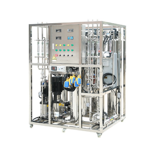
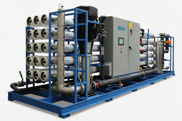
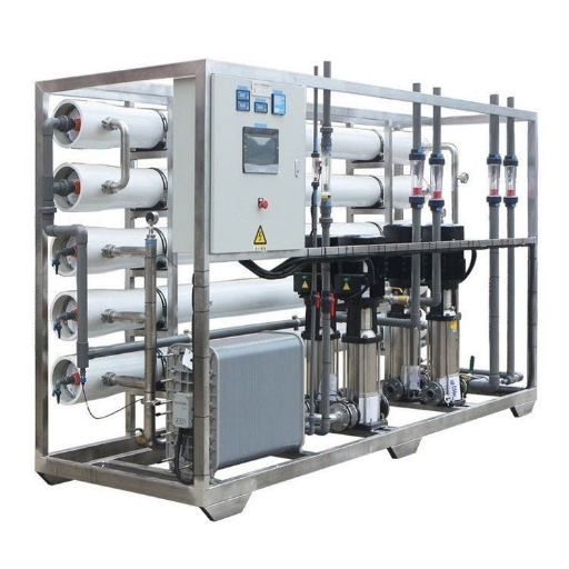
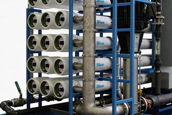
Elements are only half the answer – recovery is won or lost at system level. We build packaged brackish water reverse osmosis systems from 1 to 500 TPD, skid-mounted or containerized, with the controls that keep a high-recovery design honest in the field.
System technical data
| Feed water TDS | ≤ 10,000 mg/L |
|---|---|
| Product water TDS | ≤ 500 mg/L |
| System desalination rate | ≥ 98% |
| Recovery rate | 50–75% |
| Operating pressure | 150–250 psi (1.0–1.7 MPa) |
| Water temperature | 5–45 °C |
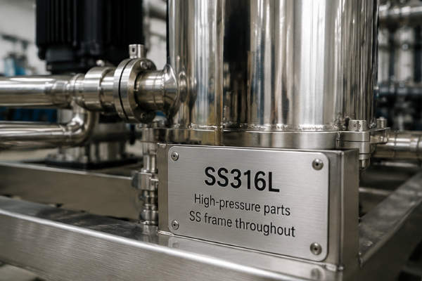
| Frame / high-pressure parts | Stainless steel / SS316L |
| Control | PLC + relay, one-button auto |
Applications & Control
An online conductivity meter watches product water quality in real time, and automatic timed flushing sweeps the membranes to extend service life – both directly protect a high-recovery setpoint. A high-pressure pump drives the reverse osmosis membranes at roughly 200 psi, and energy-recovery devices trim the energy consumption that climbs with recovery. High-pressure, low-pressure, and motor-overload protection are standard.
Applications run across industrial process water, boiler feed treatment, cooling-tower make-up, food and beverage, power and energy plants, irrigation, inland community drinking water, groundwater and well water treatment, and wastewater reuse – turning brackish source water into fresh water and potable water at plant scale for commercial and industrial applications. These industrial water treatment applications all demand purified water at a stable recovery. As a large capacity reverse osmosis system, a single BWRO system replaces a rack of small commercial reverse osmosis skids, and Blue Membrane builds these industrial reverse osmosis systems to hold recovery steady in production.
Municipal high-recovery reuse pilots – from batch-RO to flow-reversal arrays – show the same design logic scaling to utility volumes, whether the target is a compact commercial RO system or a 500 TPD plant.
TCO Advantage · Silver
Where high recovery pays back
Every point of recovery you gain is feedwater you never pump and brine you never dispose of. Because higher recovery cuts both the intake volume and the concentrate you send to disposal, operating cost falls as recovery rises – and inland brine handling is often the single largest ongoing line item.
- Less feedwater drawn per unit of product water
- Lower concentrate volume lower brine disposal cost (largest inland OPEX driver)
- Energy-recovery devices reclaim up to 30% of pump energy at high recovery [US10864481]
- Z1 anti-fouling surface stretches cleaning intervals and membrane life
Exact payback depends on your feed chemistry, tariff, and disposal route – request a site-specific TCO projection.
Have a flow rate and feed TDS in mind?
Get a Sizing Estimate →Certifications & Build Standards
Trust in a high-recovery build come down to what the steel and the test bench can prove. Below are the standards Z1 elements and Blue Membrane systems are designed and tested against – stated as verifiable specifications, not badge theater.
SPEC 01 / 04
SS316L
High-pressure parts; SS frame throughout
SPEC 02 / 04
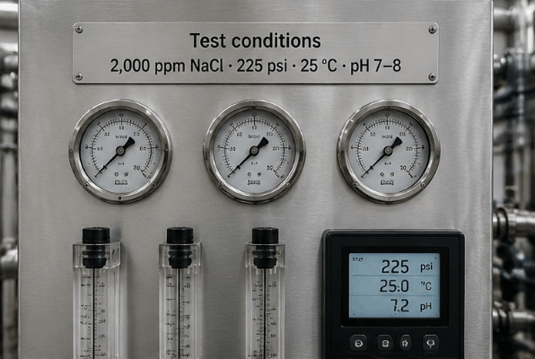
Test conditions
2,000 ppm NaCl · 225 psi · 25 °C · pH 7–8
SPEC 03 / 04
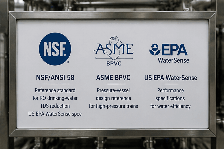
NSF/ANSI 58
Reference standard for RO drinking-water TDS reduction US EPA WaterSense spec
SPEC 04 / 04
ASME BPVC
Pressure-vessel design reference for high-pressure trains
Procurement Guide: Sizing, Lead Time, OEM & Global Supply
Selecting a brackish water RO system is really an exercise in estimation, rather than a catalog order. Since cost is derived from design, the real answer to “how much is it” is an enumeration of elements, and a quotation developed based on your specifics.
We know where Procurement goes wrong with the cost of treating water. Sticker prices, not life-cycle cost, are what the teams look at – an element that cost half as much but failed after 2 years is a lot more expensive. Blue Membrane build Z1 to last the life-time, since life-cycle costs not purchase costs determine your investment; unlike catalog houses we quote to your specific feed-water analysis.
What drives the quote
- Design capacity (1–500 TPD) and required recovery rate
- Feed TDS and dominant scale species (sets array staging)
- Element count and size 8040 / 4040 / 4021 / 2540
- Configuration: skid-mounted, containerized, split, or modular
- Control and monitoring scope (PLC, conductivity, remote)
On the lifespan: Normally, brackish RO membranes are used 3-4 years (or even more when there’s careful use on scaling) while system frame could be used 15-20 years. Reduced cleaning frequency directly extends brackish membrane service life [US6537456B2]. The source for original supply and replacement parts for Z1 is same, because Z1 is manufactured internally.
Blue Membrane serves system integrators, OEMs, and distributors throughout the globe in membrane size ranges 8040, 4040, 4021, and 2540. We’ll provide a design-based quotation, not a ball park estimate – so give us your feed analysis and the target output.
BWRO High Recovery Design Tools
Professional design and estimation tools for brackish water reverse osmosis systems, covering recovery rate calculation, system design estimation, and DuPont cross-reference selection.
Frequently Asked Questions
Brackish water RO recovery is commonly held below 75%, rising toward 80% only when feed TDS is low. We design to that band because pushing higher raises scaling, salt passage, and operating pressure faster than it returns water.
Z1 elements accept feed up to 10,000 mg/L TDS, SDI up to 5, free chlorine below 0.1 ppm, and continuous pH 3–10. Meeting these with proper pretreatment is what lets a high-recovery design stay stable.
Yes. MB-Z1-8040 is built to drop into BW30-400/34 positions and the PLUS matches BW30HR-440, both in standard 8040 dimensions, a like-for-like swap with no array redesign.
No. Above the safe limit for your feed chemistry, higher recovery accelerates membrane scaling, increases permeate salinity, and raises energy cost. The engineering goal is the highest recovery your feed supports safely, often 75% — not the highest number possible.
Yes. Systems are engineered from 1 to 500 TPD in skid, containerized, or modular form, and Z1 replacement elements in 8040/4040/4021/2540 sizes are produced in-house for dependable spare supply.
Blue Membrane brackish water RO systems are designed for feed TDS up to 10,000 mg/L. Above that band the feed move into seawater RO territory, the BWRO vs SWRO crossover, and we route the project to a seawater array design.
Yes. Blue Membrane serves international markets through system integrators, OEM partners, and distributors, supplying both packaged systems and Z1 spiral-wound elements worldwide.
Trending now