Get in touch with Blue Membrane Company

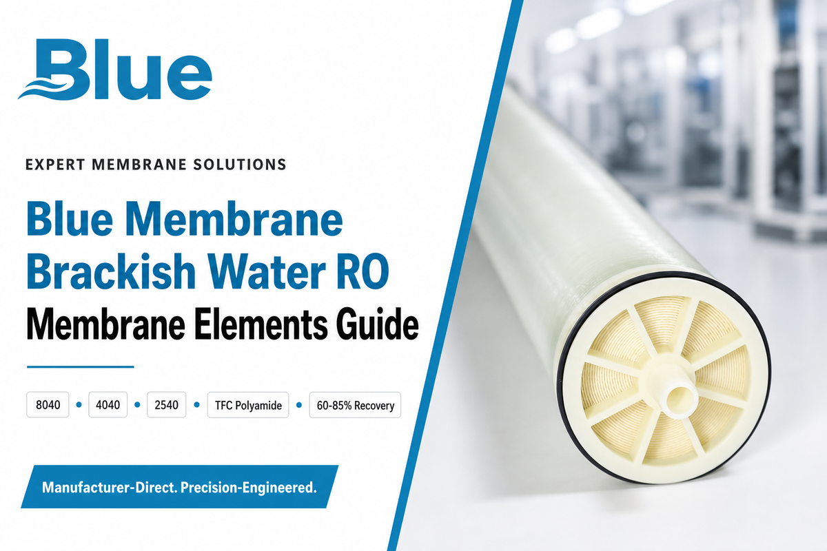
Updated July 2026. Brackish water RO membrane elements are spiral-wound filtration assemblies used to produce desalinated fresh water from brackish groundwater, well water, and process water. They fall into a unique engineering middle-ground: a specific, relatively narrow window of pressures and chemistry compared to either household tap-water filter counterparts, or full seawater RO desalination membrane equivalents.
In this Guide, you’ll learn: what goes inside them how to size and specify them what causes fouling and how to mitigate it when to replace them and what’s next on the technology front – in parallel with the release of our Brackish Water RO Membrane Elements product line, intended for those readers who require engineering detail behind the product numbers they select.
Quick Specs
| Feed TDS range | 1,000–10,000 mg/L (brackish classification) |
| Feed pressure | 30–150 psi (low-TDS end) up to 200–600 psi (high-TDS end) |
| Salt rejection | 99–99.8% typical for TFC polyamide elements |
| Recovery rate | 60–85% single-pass, industrial/commercial systems |
| Standard sizes | 2.5″x40″, 4″x40″, 8″x40″ |
| Typical service life | 2–5 years typical, up to 7 years with strong pretreatment |
What Is Brackish Water, and Why Does It Change RO Membrane Design?
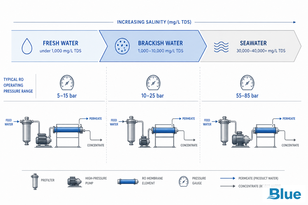
On the salinity scale, brackish water falls between fresh water and seawater, and that in-betweenness is the very reason brackish water RO membrane elements are an entire category unto themselves and don’t just adopt one of the two extremes. Total dissolved solids (TDS) levels in brackish water usually range from 1,000 mg/L to 10,000 mg/L – enough dissolved-salt impurity to be undrinkable but nowhere near the 35,000 mg/L TDS associated with seawater.
There’s a point here we might as well get out of the way early on. Not everyone uses the same cutoff point for brackish water. Some of your vendor data will cite an earlier beginning to this threshold in the area of 500 mg/L.
Some old patent data for interfacially synthesized RO membranes from the 1980s put brackish feed between 3,000 and 10,000 parts per million. But since the Texas Water Development Board-a state agency which has some actual hands-on work with the brackish ground water resource-states that “brackish” ground water can be up to 10,000 mg/L (and this is the number the present guide is using as a reference with the caveat that brackishness is a matter of practice, not pure science), that’s what we’re using. Your choice of chemistry and pressure rating isn’t defined by the cutoff, but by the TDS level of your feed in determining whether you want water that’s partially cleaned of contaminants, or purified water.
The chemistry is all the same in industrial reverse osmosis water treatment systems, reverse osmosis water systems that work on city water, and reverse osmosis water purification systems that are meant for commercial application; brackish water reverse osmosis systems are just the mid range, between pure fresh water systems and high saline content water purification systems, within that one general technological area.
Q: What is the difference between tap water and brackish water membranes?
Reverse osmosis membranes designed for tap water handle feed TDS up into the hundreds of mg/L at 60-150 psi. Brackish water elements use the same fundamental thin-film composite polyamide technology, but are built to run at higher pressures and accommodate feed TDS in the thousands, with a feed spacer geometry adapted to that higher fouling load.
Standard industrial housings come in 2.5, 4, and 8 inch sizes.
Running a tap water element at true brackish conditions would cause it to foul up and fail quickly, while running a brackish element at tap water conditions works but wastes the capacity you already paid for.
⚠️ Important
The brackish RO elements were never intended to desalinate seawater; they are constructed to handle much lower pressure levels and offer a different balance between rejection rate and product flux rate. Feeding seawater concentrations through a brackish RO element may exceed its mechanical limits and compromise the rejection rate. Any application with feed TDS greater than 10,000-12,000 ppm will require seawater-type membranes rather than a more capable brackish RO element.
Spiral-Wound Construction: What’s Actually Inside the Element
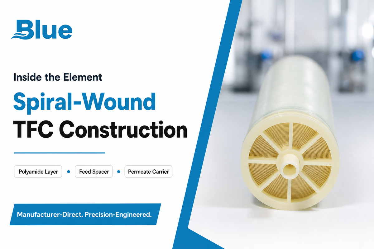
The architecture of almost all of the industrial brackish water reverse osmosis membrane element you see today is fundamentally identical: a thin-film composite (TFC) membrane, shaped into a sheet that’s then spiral-wound into a package that fit over a center permeates (treated water) tube. Even in the published membrane science community research – including a 2022 Frontiers in Chemistry article on the whole RO life cycle – you see descriptions that are common across membrane producers: a polyester mesh support, an underlying polysulfone microporous layer, and finally the salt-rejecting thin film polyamide layer.
Water under pressure is introduced to the element and sweeps across the surface of the membrane tangentially, due to a mesh feed spacer. It’s the swirling motion created in the cross-flow operation that prevents fouling and sticking of the membrane to as great a degree as is found with a dead-end type filter. Water passing through the polyamide membrane and into the central permeate tube swirls inward to collect.
A rejected stream of highly concentrated water leaves the element from the opposite end, and this reject may feed a second element within the same pressure vessel or exit as brine.
There’s a small but actual research area on compaction resistance under constant, high pressure, which may seem to many like a settled matter. Wu et al., Nature Communications (2025), reported in thin film crosslinked (TFX) membranes, “the traditional TFC skin layer undergoes significant compaction and reduction of flux with several years of operation” – a process not unlike a slow motion breakdown or failure mechanism, separate from the other common problem, fouling, which is part of why membrane chemistry isn’t done.
The risk this creates in the field is a gap between two very different symptoms that look similar on a trend chart: a facility chasing a 15% flux decline often doses more antiscalant and cleans more aggressively, assuming fouling, when the actual cause is years of gradual polyamide compaction that no chemical wash can reverse — because the fix for compaction is element replacement, not more cleaning cycles.
Element Sizing & Housing: 8040 vs 4040 vs 2540 Decision Guide
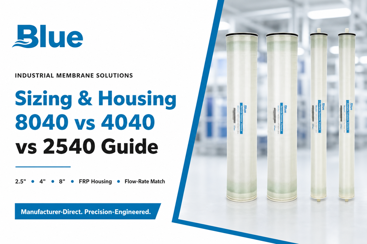
The element diameter and length is often summarized in a compound.00 means 8″ diameter, 40″ long00 4″ diameter, 40″ long00 2.5″, 40″ long. As far as size is concerned, you should select the size that deliver the required flow rate.
Element Size Decision Table
| System flow | Recommended size | Typical housing |
| Under ~15 GPM | 2.5″x40″ | Single/dual FRP housing |
| ~15–75 GPM | 4″x40″ | FRP or stainless multi-element housing |
| 75+ GPM per vessel | 8″x40″ | Stainless steel multi-element pressure vessel |
Capacity comes in gallons per day (GPD) in the case of package systems, or gallons per minute (GPM) if your system is a continuous flow one — but the principles of sizing are identical in both cases. It’s pretty simple: you save money upfront and can lift and manage by hand fewer 4″ elements (compared to an equal capacity with 8″ ones) for any given size but you’ll have more connections, more potential for leaks, and a bit more energy consumption per gallon. With 8″ elements you’ve fewer connections and use less energy per gallon at large scale, but pressure vessels are heavier and less flexible in terms of matching flow if your process flow isn’t constant.
It’s fairly common for systems to combine sizes–for instance using 4″ for first pass, and 8″ for second pass, etc. In fact, our own brackish water RO sizing tool goes through the steps, or if you just want the pressure path and element selection tool you can click through our 8040 sizing selector.
📐 Engineering Note
Things you should know about industry history: Why 4- and 8-inch elements?
In part, because a group of companies led by Koch Membrane Systems was trying to drive down per-gallon energy consumption and the count of connections by developing larger format elements. This eventually led to the 8-inch being adopted as the large-industrial standard. Just because “bigger is better” isn’t a given for a small plant, though — an 8-inch housing that’s sized for twice the flow rate you’ve will operate in the low-efficiency, part-load range.
Understanding Membrane Interchangeability & Industry-Standard Footprints
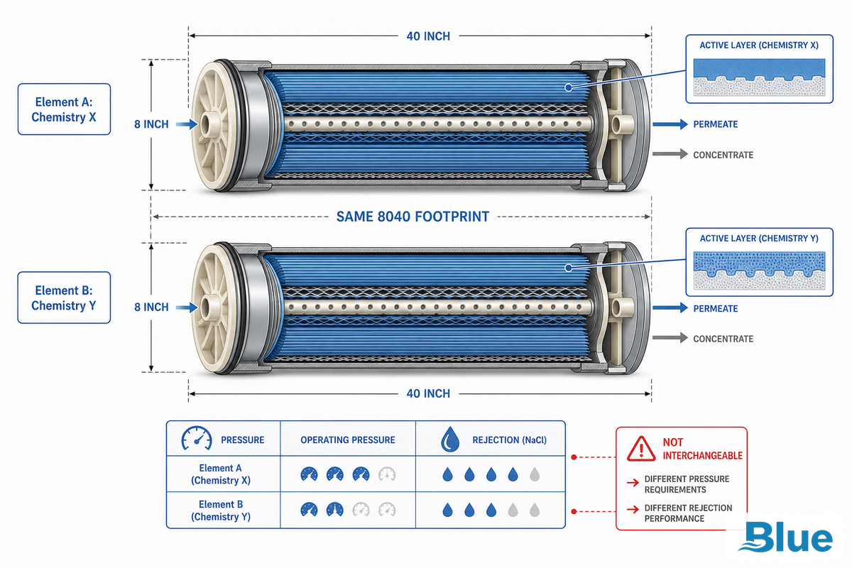
Since 4- and 8-inch element dimensions are a standard market convention rather than a proprietary design of a particular manufacturer, element from any manufacturer can generally be loaded into the housing of any other manufacturer without any alteration. That’s one genuine benefit of the marketplace — but it’s one that’s routinely oversold.
The question, “Are reverse osmosis filters interchangeable?” deserves a direct answer — and the truth is, if you’re talking about something more than physical fit, retailers who must address “incompatible filter” complaints will agree: the answer isn’t always. What actually matters is hidden inside the filter, not visible from the outside.
Two filters that are both labeled “8040” and are therefore designed to fit into the same 8-inch, 40-inch element length fiberglass housing may differ dramatically in chemistry, chlorine resistance, flux rating and energy consumption under the specific operating conditions of your water. One filter that fit physically may not be remotely equivalent if it’s rated for a higher flux or has different tolerance for oxidants, even though it screws into the same housing.
This isn’t just a theoretical risk. A common mistake is swapping in a nominally-equivalent element purely because it fits the existing housing — the problem is that two elements can both be built to the same 8040 footprint yet differ in active-layer chemistry, so in the field a facility making this swap can end up running 30-50 psi higher than the system was engineered to handle, or watch rejection drift 1-2% below the original design, because the housing spec alone never captured that difference. Neither failure mode shows up on a dimensional comparison — both tend to surface on the SCADA trend a few weeks later, usually as a support call rather than a planned change.
The upshot is: use housing compatibility as your starting point, not the end game. If you need an identical model to model replacement, then our housing cross-reference finder and compatibility cross-reference chart will match elements on the actual performance parameters you need, not just footprint.
Some of the most well-known industrial element brands that follow this housing footprint standard are the FilmTec family of membranes from DuPont (previously Dow FilmTec), often generically referred to as FilmTec brackish water filters, and the TFC membranes from a wide variety of manufacturers, such as Applied Membranes, that are compatible at the housing level with the above reservations.
Fouling & Scaling in Brackish Water: Mechanisms and Pretreatment
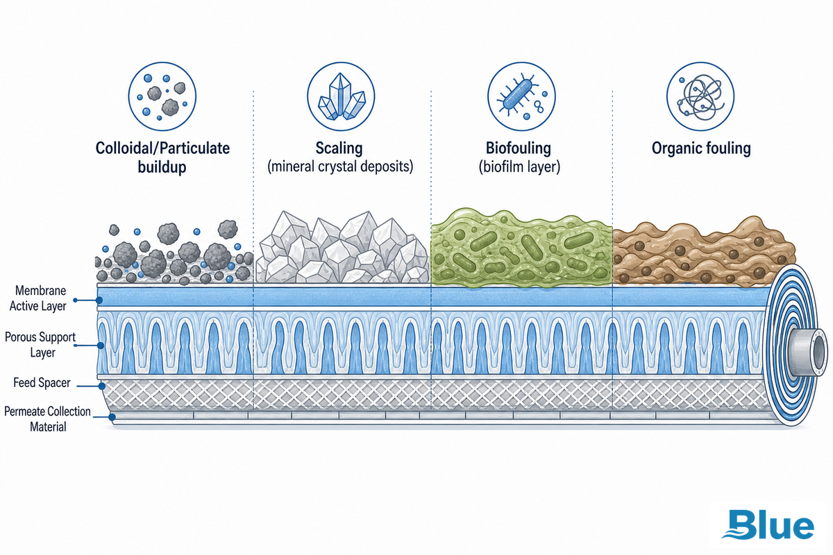
Of all factors that contribute to premature failure of brackish RO elements, fouling is by far the most significant — a recent peer-reviewed review plainly sums up fouling’s impact: Fouling is known to reduce both the lifespan and permeability of RO membrane modules while increasing operation costs due to elevated operating pressures and chemical cleaning.
Given that well water and industrial process streams tend to contain more organic and inorganic contaminants than municipally treated water, these sources bring a complex mix of potential fouling risks.
Q: What pretreatment methods are commonly used in brackish water RO systems?
Pretreatment trains for brackish water typically combine several stages matched to the dominant fouling risk: multimedia or cartridge filters remove suspended solids, antiscalants prevent scale formation, and acid or base dosing controls pH to inhibit scaling. The right combination is decided by the feedwater’s actual fouling mechanism, not a generic checklist.
For sources with elevated iron, manganese, or organic contaminants, additional pretreatment such as oxidation-filtration or ultrafiltration is also used. Choosing the right combination hinges on the actual mechanism causing fouling in your feedwater, which is why a fouling assessment should come first rather than simply selecting a generic pretreatment scheme.
To clarify those qualitative observations, we’ve developed the Brackish Water Fouling Risk Ladder:
| Fouling type | Risk indicator | Pretreatment response |
|---|---|---|
| Colloidal / particulate | SDI > 5 (per ASTM D4189-23) | Multimedia or cartridge filtration ahead of RO |
| Carbonate/sulfate scaling | Positive Langelier Saturation Index (LSI) | Antiscalant dosing, pH adjustment |
| Silica scaling | Reactive silica approaching saturation at system recovery | Recovery-rate limiting, silica-specific antiscalant |
| Iron/manganese fouling | Dissolved Fe/Mn present in well-water feed | Oxidation + filtration ahead of RO |
| Organic/TOC fouling | Elevated total organic carbon | Coagulation/filtration or UF pretreatment |
| Biofouling | Rising differential pressure with normal SDI | Biocide dosing or UV, feed disinfection review |
| Calcium carbonate scaling | Hardness + alkalinity above antiscalant design limit | Softening or acid dosing ahead of RO |
| Sulfate scaling (BaSO4/SrSO4) | Barium/strontium present with sulfate in feed | Sulfate-specific antiscalant, recovery limiting |
| Chemical/oxidative attack | Residual chlorine present without dechlorination | Dechlorination (carbon or bisulfite) ahead of TFC element |
Source and caveat: fouling-mechanism framing draws on peer-reviewed fouling research (PMC10102236) and ASTM D4189-23 for SDI methodology. ASTM’s own scope notes that SDI values can vary with water temperature and membrane filter manufacturer – so treat SDI/LSI thresholds as directional risk indicators within a consistent testing setup, not as universally portable absolute numbers across labs.
Operating Parameters: Pressure, Recovery Rate & Rejection Benchmarks
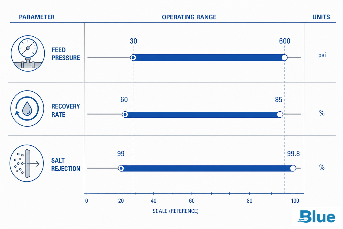
Brackish water’s own TDS range is wide enough that a single pressure number is misleading. Lower-TDS brackish feed runs closer to standard tap-water pressures – roughly 30 to 150 psi, per industry sources on fresh-and-brackish RO applications. Higher-TDS brackish feed climbs toward 200 to 600 psi. Both bands stay well under the 800-1,200 psi range that seawater-rated membranes require – a 2010 AMTA technical paper on high-TDS operations notes that once feed climbs past roughly 12,000 ppm, systems typically shift to seawater-rated membranes entirely rather than pushing a brackish element harder.
Worked Example: Estimating Concentrate TDS at a Target Recovery
A simple concentration-factor calculation shows why recovery rate and feed TDS interact directly. Concentration factor (CF) at recovery rate R is approximately:
CF = 1 / (1 − R)
At 75% recovery: CF = 1 / (1 – 0.75) = 4. So a well feeding the system at 3,000 mg/L TDS produces a concentrate stream around 12,000 mg/L – which is exactly the threshold where AMTA’s guidance says you’re leaving brackish-element territory and should be evaluating seawater-rated hardware or a lower recovery target instead. Run the same feed at 60% recovery (CF = 2.5) and concentrate stays near 7,500 mg/L, comfortably inside brackish-rated limits.
Salt rejection for thin-film composite brackish elements typically runs 99-99.8%, and that number should hold steady over the element’s service life if fouling and scaling are controlled – a declining rejection trend, independent of any physical damage, is itself one of the signals covered in the replacement checklist below. On the energy side, a Congressional Research Service report puts typical brackish RO energy intensity at 0.5-3 kWh/m3 — meaningfully lower than seawater desalination, which is a big part of why brackish systems can run at the lower end of the pressure band above. Use our BWRO design recovery estimator to run this calculation against your own feedwater numbers.
“The single most common brackish RO sizing mistake we see is chasing a headline recovery percentage without checking what it does to concentrate TDS and scaling risk at that specific feedwater chemistry. Recovery and pretreatment budget are the same decision, not two separate ones.”
Industry water treatment engineering practice, membrane system design review
When to Replace a Brackish Water RO Element: Signals & Typical Service Life
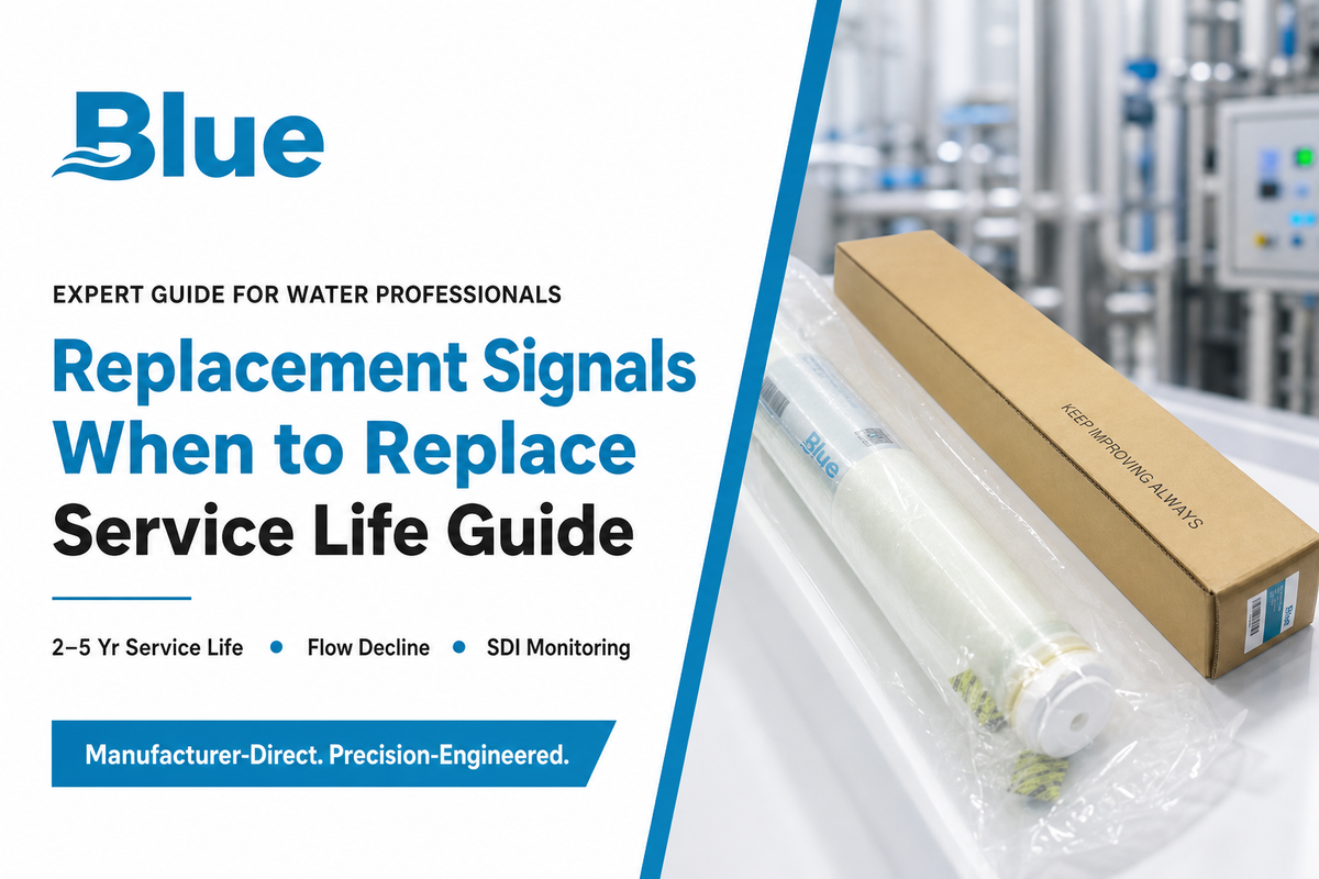
Industrial brackish water RO elements typically deliver 2 to 5 years of service life, with well-pretreated systems and disciplined cleaning schedules stretching toward 7 years – a range independently consistent with field experience shared by water treatment practitioners, who report that “3 to 5 years is readily achievable in non-fouling feedwaters or with good pretreatment.” The spread mostly comes down to feedwater consistency and how quickly fouling problems get caught.
Rather than replacing on a fixed calendar, use the 5-Signal BWRO Replacement Checklist below – each signal is a specific, trackable threshold rather than a vague “it’s probably time” judgment call:
- Normalized permeate flow decline of 10-15% or more from baseline, sustained after cleaning
- Salt passage increase of 10% or more from baseline (i.e., rejection trending down)
- A normalized pressure drop increase of 15% or more across the element or stage
- Ongoing elevated feed SDI (tracked per ASTM D4189-23) which cleaning cycles can no longer reset
- Visual fouling/scaling on a pulled element which doesn’t wash out with standard CIP
One or two signals trending alone is often indicative that cleaning is warranted, not replacement. If two or more signals remain consistently after a proper clean-in-place cycle, this is strong indication that the element itself, not just the feed conditions, have reached end-of-service-life.
A costly mistake is treating cleaning as the default response to any performance dip. A plant that runs three or four extra CIP cycles chasing a fouling problem that’s actually terminal compaction wastes chemical spend and downtime it can’t get back, in the field, without ever restoring flux — because the underlying membrane, not the surface fouling, is the problem.
Where Brackish Water RO Elements Are Used: Well Water, Municipal & Industrial Process Water
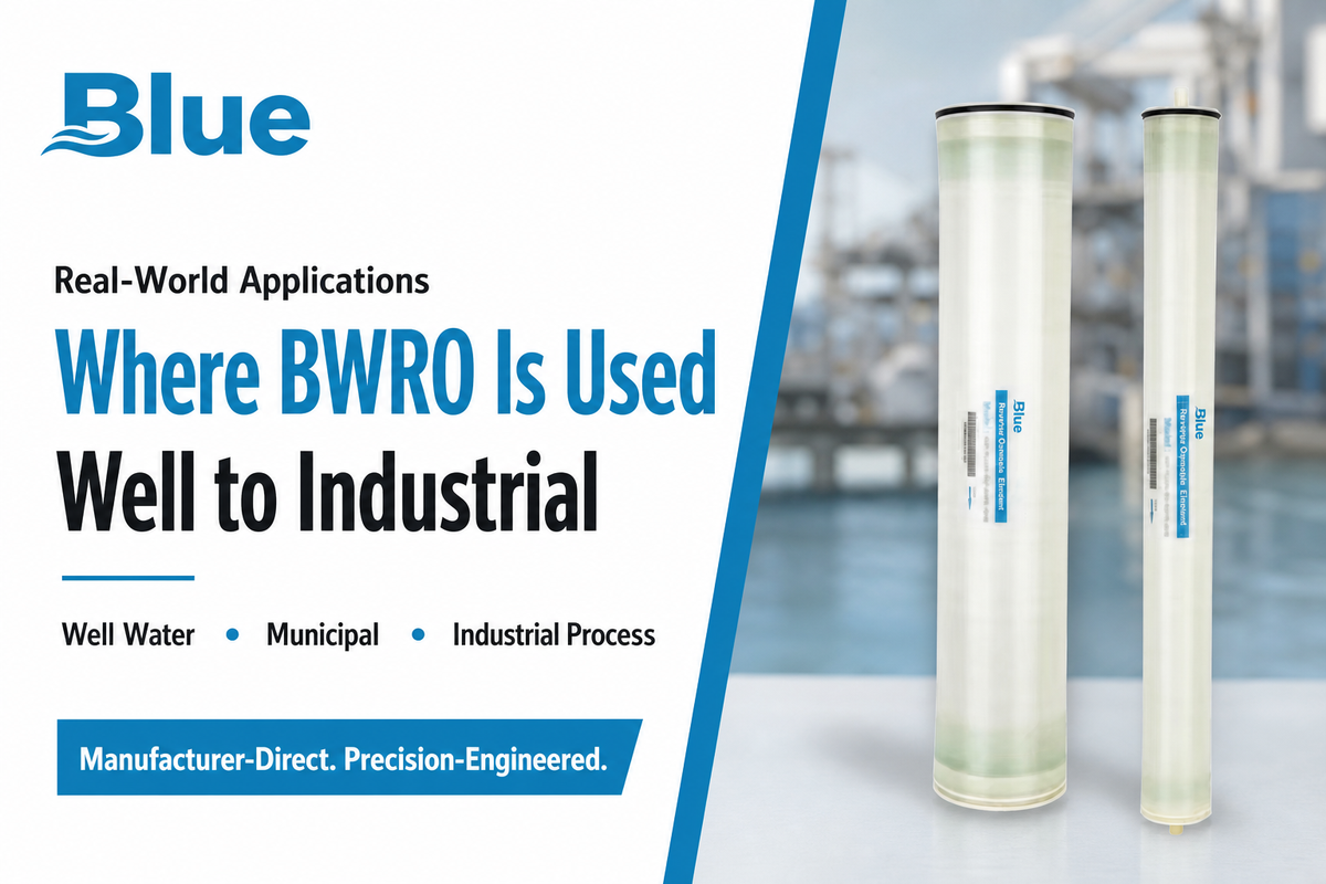
Well water is perhaps the most common brackish RO application, and it has one unique complication: unlike municipal feeds with fairly constant chemistry, well water TDS and dissolved minerals can vary with drawdown, season, and aquifer conditions, which is why an ongoing fouling assessment — not a one-time water test — should drive the pretreatment design.
A common mistake here is sizing a well-water system against a single test taken at commissioning, then finding 18 months later that seasonal drawdown has pushed TDS up 20-30% and the pretreatment budget no longer matches the feed. You can review our well water brackish RO treatment resources for a more in-depth overview of how this is accomplished.
Whereas municipal water treatment facilities will often prioritize consistency and regulatory compliance above raw throughput, most industrial water treatment applications – including boiler feed water, food and beverage production, general industrial reuse – primarily aim to match product water quality to the specifications required by a particular downstream process. Commercial reverse osmosis and commercial RO systems will, as a rule, be matched to the water source in front of them, not just some generic spec sheet. Most systems across these three environments rely on packaged, skid-mounted water treatment equipment once the desired throughput is identified; we recommend visiting our packaged BWRO systems line to explore options designed specifically for this spectrum of feedwaters.
Industry Outlook: What’s Changing in Brackish Water Membrane Technology
The rise of interest in brackish water RO in early 2026 DataForSEO trend data indicates the search volume for the main “brackish water ro” query growing from a relatively steady base level into the thousands per month by March 2026 – a change that’s missing entirely from the commercial sites currently dominating the rankings for that search term. We can’t cite one definitive reason for this change (and frankly, we’d rather tell you if we don’t know than try to force a narrative that fit), but we’re fairly certain about the drivers behind the increased attention this market segment is now receiving-regardless of this spike.
Increased scrutiny of groundwater contamination from PFAS (“forever chemicals”) is directing more attention to membrane technologies, as both RO and nanofiltration are among the very few that have demonstrated the capacity to reject PFAS compounds at the molecular level. (A word of caution: this isn’t as definitive a statement as it sounds. U.S. regulation for PFAS is in a genuine state of flux, with potential rulemakings on both the side of strengthening and rolling back certain limits in 2026. This makes brackish RO’s application in PFAS remediation a real and evolving consideration for groundwater system operators-not a mandate.) Any system using RO to reject PFAS must also plan for managing and disposing of the concentrated reject water that results.
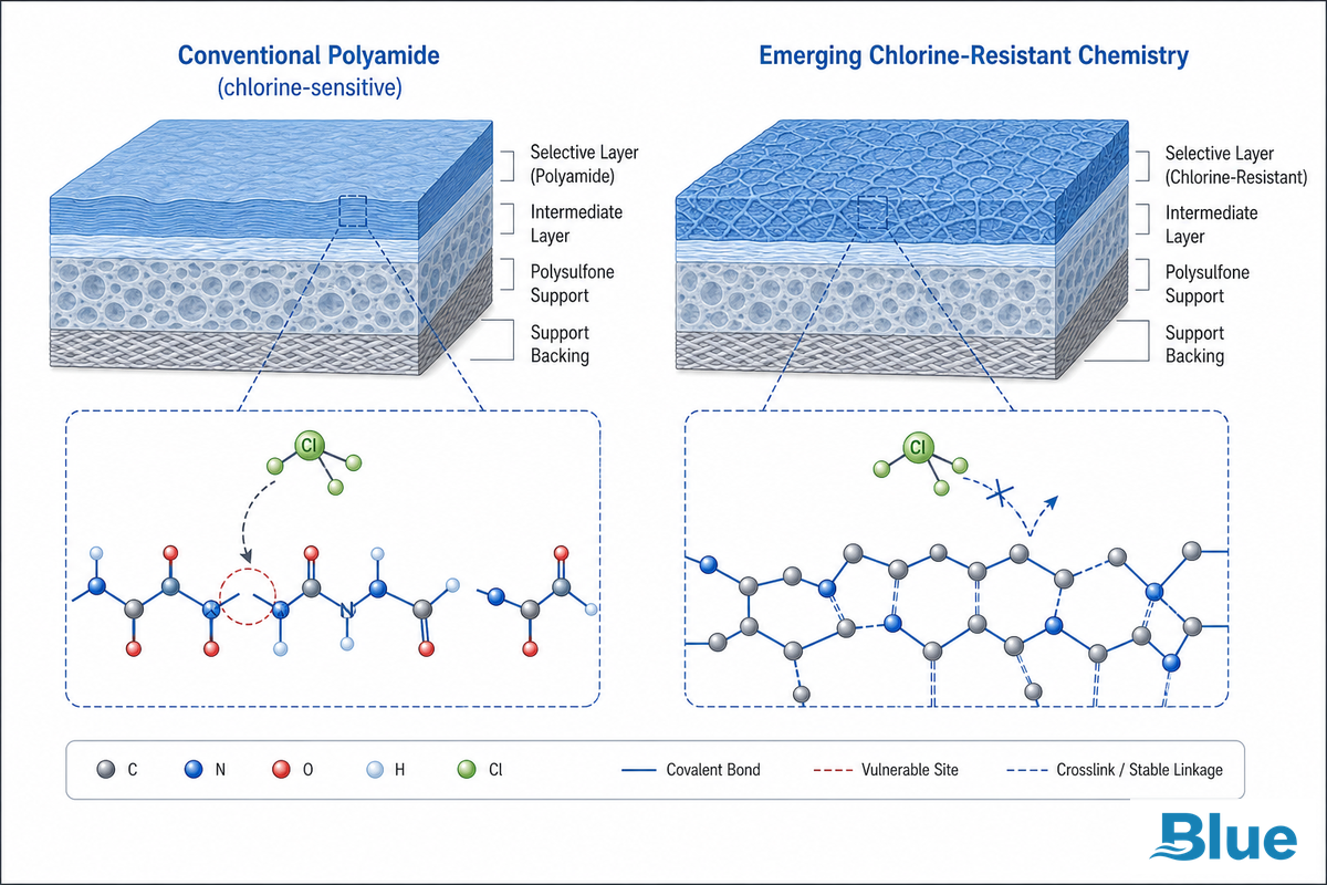
On the chemistry side, one genuinely new development worth tracking: an NSF-backed startup is developing chlorine-resistant RO membranes rated from 225 psi, aimed at eliminating biofouling without the dechlorination pretreatment step that conventional polyamide membranes require. If that chemistry matures into commercial brackish-rated elements, it would remove an entire pretreatment stage from systems currently built around chlorine sensitivity — worth watching rather than acting on today.
What this means for a buyer today is simple: if there’s a signal of PFAS in your groundwater supply or a trend of rising TDS in an aquifer, a re-evaluation of your brackish RO element choice and pretreatment design makes sense right now – as opposed to simply replacing with the same element specified many years ago. While market-size estimates for brackish desalination and broader RO membrane demand are directionally increasing in several reports from different market research firms, the broader economic backdrop is a context, not a reason to act. The reason to act is that your own feedwater is trending towards a different treatment profile than what the system was originally designed to achieve.
Frequently Asked Questions
Q: What is the typical lifespan of a brackish water RO element?
View Answer
Generally speaking, most industrial brackish water RO elements perform well for two to five years before needing to be replaced, but that range can be extended or shortened considerably based on water quality, pretreatment consistency and frequency of cleaning. Systems with high-quality pretreated water and regular cleaning schedules are on the higher end of that spectrum.
Water sources prone to frequent fouling and scaling will have much shorter element lives. Normalizing element pressure and salt passage over time is the best indicator for where any element sits in that performance window.
Q: How often should brackish water RO membranes be cleaned?
View Answer
While element life can vary from two to five years (or more), it doesn’t mean there’s a calendar that governs how often an element needs cleaning. High-quality, pretreated brackish water systems with reliable pretreatments may only require a cleaning cycle every six to 12 months, whereas more challenging water sources, whether poorly pretreated well water or a municipality’s varying source quality, might need to be cleaned every one to three months. A normalizing pressure increase or flow decline reaching a predetermined point is the real trigger, not a calendar entry.
Cleaning a system too soon is wasted chemicals and downtime. Delaying cleaning can lead to irreversibly damaged membranes.
Q: Can brackish water RO membranes be used for seawater desalination?
View Answer
No, not effective, and they typically end in premature failure when used to treat seawater. These brackish water membranes are engineered to operate at much lower pressures and lower osmotic pressures compared to seawater membranes. They generally are designed for a feedwater TDS of between about 1,000 to 10,000 ppm, and this requires lower operating pressures (30 to 600 psi).
Seawater has a high concentration of dissolved solids, typically 30,000 to 40,000 ppm and higher. Seawater-rated membranes must be built to withstand the higher operating pressures (800 to 1,200 psi) required to overcome the greater osmotic pressure and be configured with different rejection chemistry. Seawater membranes have lower water-flux capacity at brackish conditions, and brackish water membranes can suffer from element swelling and even bursting at seawater pressures.
Q: What is the difference between Thin Film Composite and Cellulose Acetate membranes?
View Answer
Rejects over 99% of the salts while cellulose acetate (older technology) membranes can only achieve about 85-95% rejection. Cellulose acetate membranes can operate over a much tighter pH range of 4 to 6 and can tolerate residual chlorine much better than TFC.
Q: How do 4-inch and 8-inch membrane sizes affect system design?
View Answer
Bigger membranes means less connections per element and less wasted energy per gallon, though they’re more expensive initially and harder to handle.
References & Sources
- Seawater and Brackish Water FAQTexas Water Development Board
- Brackish GroundwaterU.S. Bureau of Reclamation
- Thin Film Composite Polyamide Reverse Osmosis Membrane Life Cycle ReviewPMC / peer-reviewed
- Ultrahigh Pressure Compaction-Resistant Thin Film MembranesNature Communications, 2025
- Fouling in Reverse Osmosis Membranes: Monitoring, Characterization and MitigationPMC / peer-reviewed
- ASTM D4189-23: Standard Test Method for Silt Density Index (SDI) of WaterASTM International
- Brackish Water RO and NF Operations on High TDS Feed WaterAMTA technical paper, 2010
- Improvements in Spiral Wound RO and NF Membrane ElementsAMTA technical paper, 2008
Choosing the appropriate brackish water reverse osmosis solutions is simply a matter of specifying the right component for the application and water conditions, since high rejection membranes and high salt rejection BWRO elements are only good for the highest quality water when sized, pretreated and replaced properly for each unique brackish water application. Whether seeking a reliable brackish water supply from a single source, or reliable brackish water treatment across multiple brackish water sources, the underlying reverse osmosis technology is the same reverse osmosis RO membrane chemistry — what changes is how it gets specified against your specific water treatment needs.
In practice that means matching an industrial reverse osmosis membrane or a commercial thin film BWRO elements line to your specific feed water and specific water quality requirements and operation, budgeting a realistic replacement frequency instead of waiting for a failure, and treating performance and durability as a system-design outcome built on the polyester support web and microporous polysulfone interlayer inside every element, not a single spec on a datasheet. Whether the part in question is a high-performance commercial FilmTec™ brackish element or another brand’s replacement membrane, no BWRO element — however well built — can overcome a poorly designed system around it.
Why We Write This
Blue Membrane is a leading manufacturer of separation membrane technology, serving water treatment customers worldwide, including the makers of brackish water reverse osmosis products discussed here. This guide was written to help you avoid costly problems such as membrane foul, over-sized equipment and too-frequent BWRO element replacement by properly specifying a BWRO membrane from the outset. By the technical staff at Blue Membrane.
Related Articles
- Low Pressure / ULP RO Elementsfor lower-energy applications where feed TDS allows a reduced pressure design
- Seawater RO Membrane Elementsfor feed TDS beyond the brackish range covered here
- Standard Nanofiltration Membranesfor selective softening and organics removal rather than full desalination
- About Blue Membrane