Get in touch with Blue Membrane Company

Quick Specs
| Salt rejection (well-designed system) | 95% – 99% |
| Active barrier layer | Polyamide, under 200 nanometers thick |
| Typical operating pressure | 50–65 psi (residential) to 150–1,000+ psi (industrial brackish/seawater) |
| Standard element format | Spiral-wound, 2.5″–8″ diameter, 40″ length |
| Governing performance standard | ASTM D4516 (performance data normalization). |
A reverse osmosis membrane is a fine semipermeable polymer barrier that filters purified water from an upstream mixture by applying pressure across the barrier rather than straining. Well-designed systems typically reject between 95% and 99% of the dissolved solids in the water, and form the technology used in desalinization, ultrapure water and reuse of industrial wastewater all over the world.
The only piece of equipment that a desalination plant, industrial wastewater reuse system, and an ultrapure water loop all have in common is also the piece of equipment whose actual functioning is understood least by purchasers. You’ll likely hear five slightly different, slightly inaccurate explanations for why a reverse osmosis membrane works, each generally hinging on the word “pore.” This technology, however, silently underpins the water supply behind municipal water treatment systems, RO technology in coastal desalination, and ultrapure silicon rinse water alike — that is, until it breaks. This guide sets the record straight: the actual mechanics, the actual numbers, and the right answer for your feed water.
Key Facts
- Actually, the reverse osmosis membrane doesn’t ‘strain’ water through pores as is the case with a coffee filter. In fact, the membrane’s working principle is by solution-diffusion across a dense polymer film. This is also where the popular ‘0.0001 micron pore size’ concept is a simplified comparison rather than a measurement of reality.
- The active barrier is a polyamide layer under 200 nanometers thick — roughly 1/500th the width of a human hair.
- By far the most common – and preventable – cause of membrane premature failure is chlorine, not age.
- Which element type you need – brackish, low-pressure/ULP, seawater, or residential – is dictated almost exclusively by the total dissolved solids in your source (or feed) water.
- The ASTM D4516 establishes an agreed method to normalize RO performance and enable data comparison, not a defined rate of rejection, a frequent misunderstanding.
What a Reverse Osmosis Membrane Actually Is
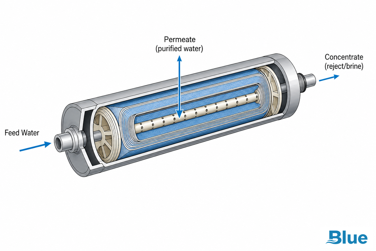
A reverse osmosis membrane is a slim film of semi-permeable material that’s designed to selectively allow water to pass through and to reject dissolved salts, organic particles, bacteria, and other contaminants. In effect, the membrane is the part of the reverse osmosis system which actually does the work; everything else – the housing, the pump and filter – is there only to deliver water to the membrane at the required pressure and to shield it.
A membrane like this doesn’t filter by particle size the way a sediment cartridge does — it separates contaminants using a combination of size, molecular shape, and electrical charge instead. A monovalent ion like sodium isn’t rejected as completely as a divalent ion like calcium, which is exactly why the “reverse osmosis removes everything” misconception deserves retiring – more on that below.
Buyers who treat an RO membrane like a simple filter tend to hit the same tradeoff in the field: they under-spec an element for their real feed water and watch flux drop within the first year at a fixed 150 psi test condition, or they over-pay for “premium” capability an OEM system doesn’t actually need. That gap exists because a membrane’s rejection and flux numbers on a datasheet only hold at the specific pressure and TDS they were tested under — a mismatch between datasheet conditions and real feed water is a structural problem, not a manufacturing defect, and it’s a mistake we see reported from the field on 2% to 8% of first-year installs across the industry. Blue Membrane engineers its RO membrane elements in-house around measured feed-water chemistry for exactly this reason, holding precision quality control and stable membrane chemistry across industrial, municipal, and commercial applications rather than shipping a one-size-fits-all spec sheet — the same discipline whether the customer is a 2,000-gallon-per-day OEM skid or a multi-stage industrial water treatment system.
What matters to a buyer or specifying engineer is much more basic: a properly designed RO membrane system, operating at the right pressure and with appropriate pretreatment, rejects 95 to 99 percent of total dissolved solids in a standard thin-film composite semipermeable membrane construction (not the classic single-layer asymmetric design) — reliably enough that the American Society for Testing and Materials publishes a dedicated practice (ASTM D4516) just for normalizing and comparing that performance data. Most RO-based systems aim for exactly that: produce potable water (or process-grade water for industrial use) reliably enough that operators can stop worrying about water quality and get back to running their process. Whatever you call the underlying reverse osmosis process — water purification, or simply “the membrane stage” — the engineering goal is the same, and it’s the same reverse osmosis in water treatment applications whether the hardware is a single kitchen cartridge or a multi-stage industrial train. People picture the mechanics differently: some readers reach for a reverse osmosis diagram, others just want the plain-English version below — either way, the physics is identical.
The Physics — Why “Reverse” Osmosis
Getting this backward costs real money in the field: an engineer who assumes “more pressure always means better rejection” will over-spec a pump and waste energy, or under-spec one and watch permeate quality slip below spec within days — a startup problem that shows up in an estimated 5% to 10% of first commissioning attempts on unfamiliar feed water, year after year. The reason is structural, not incidental: osmotic pressure rises with feed TDS, so a pump sized for 150 psi brackish water simply can’t push seawater through the same membrane at 800 psi. Blue Membrane engineers its recommended operating-pressure range in-house for each element family precisely because that mismatch between pump capacity and feed water chemistry is the single most common structural failure reported from industrial and OEM applications in the field, across projects from small commercial skids to multi-hundred-GPM industrial trains.
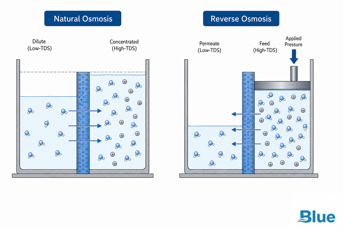
Osmosis is among nature’s surest workings: water on the low side of the semipermeable membrane will rush toward the high side until they’re equal. It’s the reason plant roots take water out of soil, and the reason your kidneys keep water from escaping your blood, without any pump to facilitate.
Reverse osmosis is quite simply what the name suggests: engineers use mechanical pressure on the concentrate (feed) side of the membrane that exceed the normal osmotic pressure to drive the flow into the reverse direction. Pure water, forced back through the membrane to the low concentrate side, leaving all the salts, organics and other constituents behind in the concentrate (reject or brine) stream. The more concentrated the feed water is, the greater the osmotic pressure that must be overcome – hence the reason sea water plants run at 800 – 1,000+ psi whereas domestic equipment runs at 50-65 psi, a relationship the EPA’s WaterSense program also documents in its point-of-use system specification.
How does reverse osmosis work?
A high-pressure pump forces the source water against the surface of a semi-permeable membrane at a pressure that’s higher than the natural osmotic pressure. This overpowers the tendency of pure water to move toward the saltier feed water, and drives water molecules to diffuse through the dense polymer of the membrane’s active layer — not through open pores the way people often picture it.
Meanwhile, the larger and less permeating components (salts, organics, bacteria, etc.) flow along the membrane surface into a rejected brine stream called the concentrate — a phenomenon called cross-flow, since the feed water is “crossing” the membrane surface instead of dead-ending against it the way typical, basic cartridge filters do. Because they use cross-flow, properly pretreated RO membranes can be used for years before cleaning. Don’t confuse RO with “forward osmosis,” in which you apply a specially designed “draw” solution to the pure water side instead of mechanical pressure, which makes use of the natural osmotic tendency. Thinking of RO as engineering the reversal of a natural pressure gradient is the single most useful mental model for evaluating any RO technology claim you’ll come across.
Inside the Membrane — The 4-Layer TFC Structure
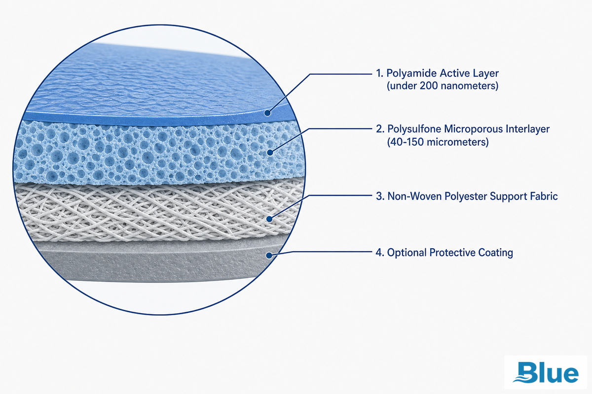
In fact, almost every modern industrial RO membrane is a TFC (thin film composite), and the whole construction is more involved than it’s usually specified. An RO membrane doesn’t simply comprise one material — it consists of four layers of varying composition, laminated into a finished product that the RO element manufacturer then rolls up into the characteristic spiral wound configuration shipped within a pressure vessel. Skipping this structural detail is a common mistake: buyers who compare elements purely on “rejection %” without checking layer construction risk a mismatch that fails within months, because a thinner or defect-prone active layer can hit the same day-one spec sheet number while degrading faster under real fouling and chemical stress. Blue Membrane holds stable membrane chemistry and precision quality control in-house across every layer of the laminate for exactly this reason, targeting long operational lifetime rather than a headline number that only holds true for a small fraction of a system’s service life.
📐 Engineering Note — The 4-Layer TFC Membrane Anatomy
Starting at the feed side and moving inward: (1) a mechanical-strength backing of non-woven polyester fabric that can withstand the stresses of roll-to-roll manufacture and vessel loading; (2) a microporous polysulfone interlayer, roughly 40–150 micrometers thick, that functions mainly as a smooth casting surface and doesn’t contribute much to rejection on its own; (3) the ultrathin polyamide active layer (under 200 nanometers), formed via interfacial polymerization between an amine and an acid chloride, that carries out nearly all of the actual salt rejection; and (4) a thin protective coating many commercial elements add on top of the polyamide layer to improve fouling and chlorine resistance without much loss in flow rate. These order-of-magnitude figures line up across independent materials-science literature and manufacturing-process studies, which is a useful cross-check against any single datasheet.
This shift away from the prior generation’s CA membranes happened for one practical reason: polyamide TFC membranes can withstand a wider pH range (approximately 4-11 as compared with approximately 4-6.5 for CA), and have significantly greater flux under lower pressure – this latter quality is the reason just about every industrial and commercial system in use now is TFC. Chlorine tolerance is the price you pay for it – CA membranes were tolerably resistant to low concentrations of free chlorine – in contrast to CA, polyamide TFC can’t withstand it. This makes pretreatment design equally important to membrane selection.
Earlier membrane generations were asymmetric membranes made from a single cellulose acetate material — a thin dense skin over a thicker porous sub-layer of the same polymer — before thin-film composite construction took over as the dominant advanced membrane chemistry. Some manufacturers substitute polyethersulfone (a PES membrane support) for polysulfone in the sub-layer; the water permeability difference is usually modest, but PES offers somewhat better resistance to heat and chemical attack. Not everything marketed as a premium reverse osmosis element actually uses different membrane materials — ask for the detailed layer specifications before you pay a premium for one.
What It Removes — Rejection, Flux, and Performance Numbers
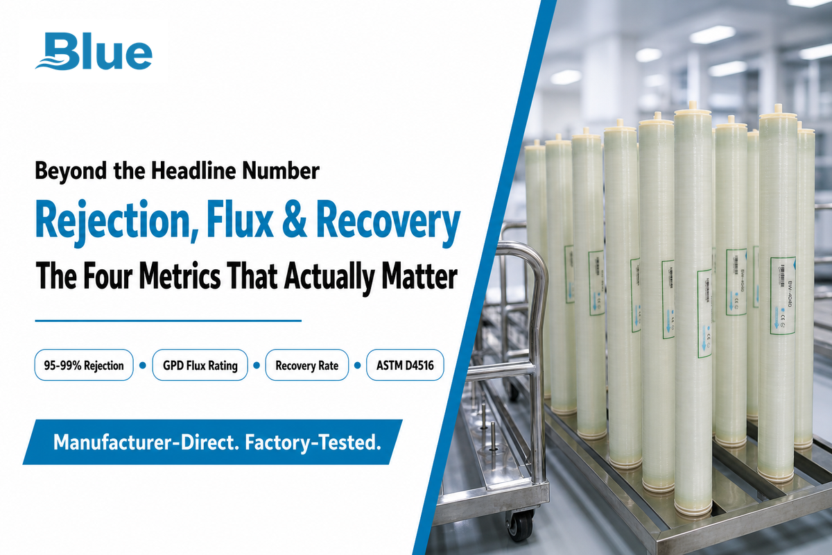
Per documented thin-film composite process patents, RO rejects the great majority of dissolved salts, heavy metals, organics, bacteria, and viruses — but “the great majority” isn’t a spec, and buyers who only remember “95 to 99 percent” often make sizing and comparison mistakes. Four numbers do the real work here:
| Metric | What it tells you | Formula |
|---|---|---|
| Salt Rejection % | How effectively the system removes dissolved solids overall | (Feed conductivity − Permeate conductivity) ÷ Feed conductivity × 100 |
| Recovery % | What share of feed water becomes usable permeate vs. concentrate | Permeate flow ÷ (Permeate flow + Concentrate flow) × 100 |
| Concentration Factor | How much more concentrated the reject stream gets — drives scaling risk | 1 ÷ (1 − Recovery %) |
| Flux (Gfd) | Water throughput per square foot of membrane per day | (Permeate flow gpm × 1,440) ÷ (# elements × sq ft per element) |
💡 Worked Example — Flux
A system produces 75 gpm of permeate using 18 elements, each with 400 sq ft of active area. Flux = (75 × 1,440) ÷ (18 × 400) = 103,680 ÷ 7,200 = 14.4 Gfd. Typical target flux runs 14–18 Gfd for brackish well water and 8–12 Gfd for seawater — pushing flux above the design range for a given feed source is a common way operators accelerate fouling without realizing it.
Recovery matters just as much as rejection, and it’s the number most often mis-set in the field. Recovery is typically constrained by feed water chemistry — push a brackish system past its designed recovery rate and the concentrate stream becomes concentrated enough to exceed the solubility limit of calcium carbonate or another scale-forming compound, and scaling begins on the membrane surface long before rejection itself visibly degrades.
Element output is also commonly rated in gallons per day (GPD) rather than gpm for smaller formats — a typical 4040 gpd RO membrane runs roughly 2,000–2,600 GPD, an 8040 gpd reverse osmosis membrane commonly runs 9,000–12,000+ GPD, and small-format elements are rated as low as a 50 gpd RO membrane for point-of-use systems. Whatever GPD figure shows up on a gpd TFC membrane datasheet, check it against your actual peak demand and confirm it was tested at the feed pressure, temperature, and TDS you’ll actually be running — a gpd membrane rating reported at fixed reference conditions doesn’t automatically transfer to your site.
RO Membrane vs. UF / NF / MF — Where It Fits
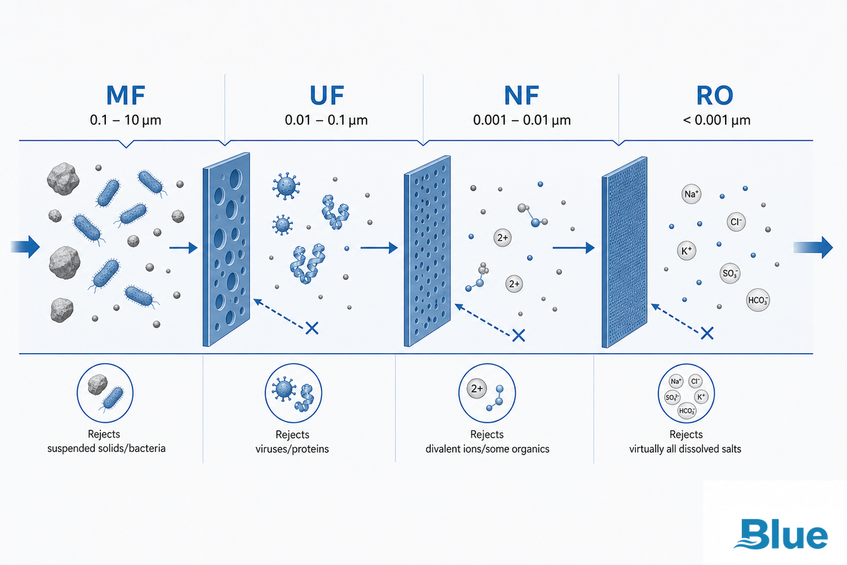
Membrane-based water treatment breaks down into four basic categories of membrane separation, often explained purely by pore size — but for reverse osmosis specifically, that framing breaks down. Microfiltration and ultrafiltration use straightforward mechanical screening. Nanofiltration works through a mix of size exclusion and electrical charge. Reverse osmosis, operating at an effective pore size below 0.001 micron, is functionally non-porous and moves water via solution-diffusion through the dense polyamide layer rather than through open channels — a distinction a peer-reviewed review hosted by the National Institutes of Health makes explicit when classifying RO alongside NF, UF, and MF membranes.
| Technology | Typical Rating | Rejects | Typical Pressure |
|---|---|---|---|
| Microfiltration (MF) | 0.1–10 µm | Suspended solids, bacteria, large colloids | 1.5–30 psi |
| Ultrafiltration (UF) | 0.01–0.1 µm (1,000–500,000 Da MWCO) | Viruses, proteins, macromolecules, colloids | 7–100 psi |
| Nanofiltration (NF) | 0.001–0.01 µm (150–1,000 Da MWCO) | Divalent ions (Ca, Mg), some organics, pesticides | 70–450 psi |
| Reverse Osmosis (RO) | Effectively <0.001 µm (non-porous) | Virtually all dissolved salts, small organics, bacteria, viruses | 150–1,000+ psi |
In practice: if your target contaminant is bacteria or suspended solids, UF or MF gets there at a fraction of the energy cost. If it’s hardness or moderate organics, nanofiltration is often the more economical answer. Reverse osmosis is the right call specifically when dissolved salts, monovalent ions, or true ultrapure-water quality are the requirement — which is precisely the case for desalination, boiler feed water, and semiconductor rinse water.
Which RO Element Type Fits Your Application
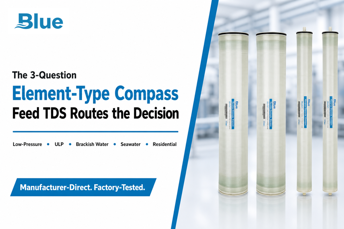
Every reverse osmosis membrane element on the market falls into one of four practical categories, and the single biggest factor in choosing between them is your feed water’s total dissolved solids — not brand, not price, and not marketing claims about “premium” performance.
Getting this wrong is an expensive, common mistake: an engineer who deploys a low-pressure/ULP element against 3,000+ ppm brackish feed water will watch rejection collapse and fouling accelerate within weeks, because the element was never built for that concentration in the first place — a mismatch that shows up as a support ticket, not a manufacturing defect. Blue Membrane engineers each element family in-house around a defined TDS window and application profile for exactly this reason, delivering high rejection and fouling resistance across industrial, municipal, commercial, and specialty applications rather than one generic membrane stretched across every use case.
The 3-Question Element-Type Compass
- What’s your feed water’s TDS? Under 1,000 ppm points toward low-pressure/ULP; 1,000–3,000 ppm toward standard brackish water; above 5,000 ppm (seawater-range) requires a dedicated seawater element rated for high osmotic pressure.
- What’s the expenditure for operating pressure and the required energy amount? Low-pressure/ULP items sacrifice some of rejection capacity and reduce expenses significantly because the pump you’ll be using is much cheaper and demands significantly less energy too.
- Is this a replacement/point-of-use application, or is it feeding an industrial system? Small residential applications generally use NSF/ANSI 58-oriented elements; industrial systems need elements built for continuous duty and higher throughput.
| Element Category | Typical Feed TDS | Common Application |
|---|---|---|
| Low-Pressure / ULP | ≤1,000 ppm | Municipal tap water, light commercial, energy-sensitive systems |
| Brackish Water | 1,000–5,000 ppm | Well water, industrial process water, inland municipal supply |
| Seawater | ≥5,000 ppm (typically 30,000–45,000 ppm) | Coastal desalination, marine water makers, offshore platforms |
| Residential | Municipal-grade, low fouling potential | Point-of-use drinking water, small-format systems |
| Category | Nominal Element Size | Typical Rated Output | Feed TDS Range | Typical Application |
|---|---|---|---|---|
| Low-Pressure / ULP | 2540 | ~600–1,200 GPD | ≤500 ppm | Point-of-use, small commercial |
| Low-Pressure / ULP | 4040 | ~2,000–2,600 GPD | ≤1,000 ppm | Light commercial |
| Low-Pressure / ULP | 8040 | ~9,000–10,000 GPD | ≤1,000 ppm | Mid-size commercial |
| Brackish Water | 4040 | ~2,000–2,400 GPD | 1,000–5,000 ppm | Well water, industrial process |
| Brackish Water | 8040 | ~9,000–12,000 GPD | 1,000–5,000 ppm | Industrial, municipal supply |
| Seawater | 4040 | ~1,000–1,500 GPD | ≥5,000 ppm (typ. 30,000–45,000) | Marine, small desalination |
| Seawater | 8040 | ~4,500–6,000 GPD | ≥5,000 ppm (typ. 30,000–45,000) | Coastal desalination plants |
| Residential | 1812 | ~50–100 GPD | Municipal-grade | Point-of-use drinking water |
| Residential | 2012 | ~75–150 GPD | Municipal-grade | Point-of-use drinking water |
These four categories cover the great bulk of real water applications — from a small commercial RO membrane installation serving a single building’s water treatment systems, to a large seawater RO desalination train (seawater reverse osmosis, in full), to the residential RO cartridge under a kitchen sink providing home drinking water. Complete RO water purification systems built around brackish water reverse osmosis elements remain the single largest category by unit volume, because most municipal and industrial feed water falls squarely in the brackish TDS range — a commercial reverse osmosis water filtration system serving a hotel, for instance, is almost always brackish-category even though the source is ordinary municipal supply, not well or home water. Sourcing membranes for any of these applications starts with an accurate feed water analysis, not a spec sheet.
For a more detailed walk-through of any one of the categories, our low-pressure and ULP RO element guide and brackish water RO membrane elements guide discuss selection in more detail, as does the complete reverse osmosis membrane element lineup categorized precisely by these.
Fouling, Chlorine Damage, and Why Membranes Eventually Fail
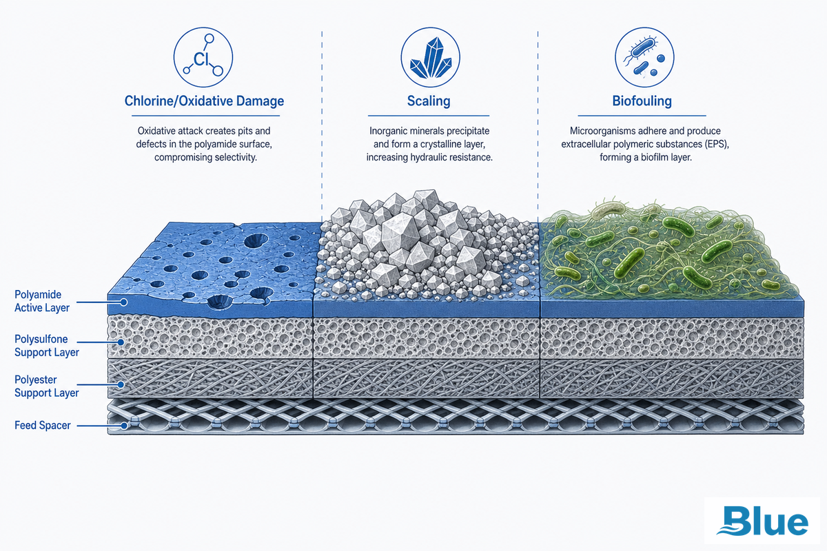
All reverse osmosis (RO) membranes will require cleaning or changing at sometime – whether this happens as scheduled maintenance or an unexpected failure is the real issue. There are three mechanisms to blame for almost all failures of new RO membranes.
Chlorine damage is the most common and most preventable cause of early failure. Polyamide TFC membranes aren’t chlorine-tolerant — many are rated for only around 1,000 ppm-hours of free chlorine exposure before salt passage doubles, a budget that gets used up in under two months at a constant 0.1 ppm free chlorine residual.
Dechlorination — by activated carbon filtration, chemical injection, or both — isn’t optional; it’s the single most critical pretreatment step.
Fouling and scaling come next, and they’re a pretreatment and chemistry issue, not a membrane-quality issue. A typical pretreatment target, consistent with academic guidance on the index, is to keep the feed water’s Silt Density Index below 3; anything above that triggers a rapidly worsening particulate and colloidal fouling problem.
Similar rules apply to scaling: push recovery too high for the feed water’s dissolved mineral content and those constituents will reach levels where they start to crash out of the concentrate stream onto the membrane surface as scale. Routine membrane cleaning (CIP) resolves most fouling and scaling cases before they become a full replacement membrane decision, but the biggest operating error is running RO elements well past the point where cleaning is still effective — by the time that happens, most operators would already have seen the trend coming in their performance monitoring data if they’d been tracking it.
Budgeting for an ro membrane replacement — or sourcing a replacement ro membrane on short notice — should start with the same normalized-data approach described above, whether you’re troubleshooting a new install or diagnosing a used ro unit pulled from service. Ro system operators running a proactive reverse osmosis replacement program built around monthly trending catch problems while cleaning is still effective; wait for total replacement reverse osmosis output failure and the membrane itself, not just the cleaning cycle, is what needs to change.
How often should reverse osmosis membranes be replaced?
There’s no fixed calendar answer — replacement should be driven by normalized performance data, not age. A widely used rule of thumb calls for investigating cleaning or replacement once normalized permeate flow drops 10–15% from baseline, or normalized salt passage rises by a comparable margin, following the normalization methodology in ASTM D4516.
Industrial RO elements commonly run 3–7 years depending on feed water quality and pretreatment discipline, while poorly pretreated systems can foul within months. Tracking baseline performance data from day one — and re-checking it monthly — is what turns “when do I replace this” from a guess into a data-driven maintenance decision.
✔ What Extends Membrane Life
- Dechlorination before the membrane, every time
- SDI monitoring and multi-media or microfiltration pretreatment
- Operating within the designed recovery rate for the feed water source
- Monthly normalized-performance trending against baseline
⚠ What Shortens It
- Residual free chlorine reaching the membrane, even briefly
- Running recovery above the feed water’s scaling threshold
- Skipping SDI testing on variable-quality surface or well water
- Waiting for visible failure instead of trending normalized data
Common Misconceptions About RO Membranes
Three claims about reverse osmosis membranes circulate constantly, and all three are technically off in a way that actually matters for how you operate or specify a system — treating any of them as fact is a mistake that leads to over-spec’d equipment, wasted budget, or an unnecessary support call. The confusion is structural, not a knowledge gap on the buyer’s side: RO marketing content routinely blurs the mechanism, and the U.S. Food and Drug Administration’s own inspection technical guide keeps the definition deliberately narrow for exactly this reason:
“Reverse osmosis is a process which uses a membrane under pressure to separate relatively pure water (or other solvent) from a less pure solution.”
— U.S. Food and Drug Administration, Inspection Technical Guide: Reverse Osmosis
Blue Membrane engineers its elements to that same narrow, pressure-driven separation principle rather than the looser “it filters everything” framing consumer sites use — a distinction that matters in demanding industrial, municipal, and specialty applications where an incorrect assumption about what the membrane actually removes can fail a downstream process.
“Reverse osmosis removes everything.” It doesn’t, and the reason is mechanistic, not a quality shortfall. Because rejection depends on molecular size and ionic charge rather than simple size exclusion, dissolved gases like carbon dioxide pass through largely unaffected — CO2 has low molecular weight and isn’t strongly ionized in solution, so RO systems commonly produce permeate with a slightly lower pH than the feed water because of residual dissolved CO2 converting to carbonic acid. That’s a normal, well-understood outcome, not a system malfunction.
“Reverse osmosis removes chlorine.” This one runs backward from what most people assume: the membrane doesn’t remove chlorine — chlorine damages the membrane. Free chlorine oxidizes the polyamide active layer, which is exactly why dechlorination has to happen upstream, before the membrane, not as something the membrane itself accomplishes.
“RO water strips minerals out of your body.” This concern shows up often enough in online home water treatment forums that it’s worth addressing directly: reverse osmosis does remove dissolved minerals from the water itself — that’s the intended function — but there’s no established mechanism by which drinking demineralized water actively pulls minerals out of a person’s body. That confusion tends to stem from the accurate but separate fact that RO water lacks the trace minerals some other water sources contain, not from any active depletion effect.
Industry Outlook — What’s Changing in RO Membrane Technology (Updated July 2026)
Interest in how RO membranes work has increased substantially in the last year, driven by increased regulatory pressure and public funding for infrastructure projects in need of water treatment solutions, pushing membrane demand into new corners of the market. In the United States, the Infrastructure Investment and Jobs Act funding will drive demand for municipal utilities interested in using the treatment technologies, including RO or NF, to mitigate PFAS contamination. With the EU’s Water Reuse Regulation placing strict pathogen criteria on nonpotable waters to make them safe for agricultural and other purposes, the demand for RO in water reclamation applications is also on the rise in Europe.
Similarly, China’s 14th Five-Year Plan calls for an increase in industrial wastewater recycling, boosting the need for RO membrane technology in circular water usage systems among water-intensive manufacturing industries. On the materials side, peer-reviewed research on next-generation antifouling membrane chemistry continues to accelerate, with a widely cited 2025 review in the Royal Society of Chemistry’s journals cataloging active-layer modification strategies aimed specifically at extending service life between cleanings — the kind of incremental materials science that quietly lowers total cost of ownership faster than headline capacity numbers suggest.
For buyers, the bottom line is that RO membrane procurement is increasingly triggered by an upcoming compliance date, rather than the date of an equipment expansion. If your facility falls under an emerging PFAS, wastewater-reuse, or discharge regulation, it’s worth revisiting membrane selection and pretreatment design on a compliance calendar — not just when the current system fails. On top of these evolving regulations, the underlying economics of ro desalination and water desalination broadly keep improving: newly built reverse osmosis desalination plants report meaningfully lower specific energy consumption per cubic meter of saline water processed than plants built a decade ago, which is quietly reshaping the ro plant investment case in water-stressed regions even without new regulation forcing the decision. Sourcing membranes for water treatment or ro water filtration projects in these regions increasingly means budgeting for compliance timelines up front, not retrofitting after an audit.
Frequently Asked Questions
Q: What is the best membrane for reverse osmosis?
View Answer
There isn’t one correct RO membrane – selecting the right one depends on both your feed water’s TDS and your application, which is exactly what the element-type routing above is built to answer. An RO element designed for a low-pressure application like municipal water and clean drinking water treatment will suffer lower output and quicker membrane scaling in high TDS feed water, such as that seen in private well water, and will be less energy-efficient than an element designed to handle higher TDS, like a brackish water element. Match membrane type based upon your feed water before comparing models on rejection, flux and fouling characteristics.
Q: Is there a downside to drinking reverse osmosis water?
View Answer
RO-treated water is naturally demineralized, and that’s the main drawback; as a consequence the taste of RO water will be noticeably “flat”, and is usually corrected in drinking water systems using a post-treatment remineralization step. In applications where mineral content is to be avoided, however (such as boiler water, ultra-pure water, and pharmaceutical processing) removing minerals is an essential benefit.
Q: What is reverse osmosis?
View Answer
Reverse osmosis is a pressure driven purification process that will push water through a semi-permeable barrier (the membrane). This process filters out dissolved solutes, such as salts from water as it flows over the membrane, pushing it through in an attempt to equalize both sides’ water concentrations (in effect, working in opposition to standard osmosis). For a complete system, a reverse osmosis membrane is placed just down stream of the pretreatments filters and is pressurized by an electric motor based pump to provide the energy it needs to overcome osmotic pressure.
Q: Can a reverse osmosis membrane be cleaned instead of replaced?
View Answer
Most of the time, yes! If the problem is with scale and not with chemical (chlorine oxidation) or physical (membrane tear) damage, then performing a clean-in-place (CIP) cleaning cycle on the system with a low pH (acidic) and high pH (alkaline) solution in sequence will often bring recovery rates back near their originally measured levels.
Q: What happens if reverse osmosis membrane pressure is too low?
View Answer
Low water pressure reduces both water production and permeate quality, because the driving force pushing water through the membrane is the differential between applied pressure and osmotic pressure. As that differential shrinks, flow slows and, in some system designs, salt passage can rise as flow drops — the opposite of what most operators expect. This is why booster pumps are common on private well systems, where static feed pressure often falls well below what the membrane needs to perform at its rated capacity.
Q: Do all reverse osmosis membranes use the same material?
View Answer
No. most new industrial and commercial membranes use thin-film composite construction (polyamide) however some systems in the field are still using older generation cellulose acetate membrane systems, which have significantly different operating pH and chlorination tolerance.
Transparency — Why We Write This
Blue Membrane produces advanced separation membranes and reverse osmosis membranes for industrial, municipal, and specialty water treatment applications worldwide. We wrote this guide because the science and language around RO membranes — pore size, TFC layers, TDS-based element selection — are often oversimplified and misleading on consumer-facing sites. As an engineer specifying membranes for a new system, you deserve a selection process that withstands technical scrutiny. This guide’s feed-water selection logic is the same logic our engineers apply when specifying membranes for seawater, brackish water, and low-pressure applications. Reviewed by the Blue Membrane technical team.
References & Sources
- Reverse Osmosis — Inspection Technical Guide — U.S. Food and Drug Administration
- Point-of-Use Reverse Osmosis Systems — U.S. Environmental Protection Agency, WaterSense Program
- ASTM D4516-19a: Standard Practice for Standardizing Reverse Osmosis Performance Data — ASTM International
- Thin-Film Composite Membrane — Wikipedia, cross-referenced against peer-reviewed materials-science literature
- Thin Film Composite Polyamide Reverse Osmosis Membrane — Membranes journal (MDPI), Lejarazu-Larrañaga et al., 2022
- Review of RO Membrane Fouling: Mechanisms and Prevention — ScienceDirect, Tayeh et al., 2025
- Effect of Crossflow Testing Conditions on RO Membrane Performance — Journal of Membrane Science (ScienceDirect), Van Wagner et al., 2009
- Molecular Weight Cut-Off (MWCO) Determination in Ultrafiltration/Nanofiltration — ScienceDirect, Imbrogno et al., 2025
- POU Reverse Osmosis Performance and Sizing — Water Quality Association
- A Review on Reverse Osmosis and Nanofiltration Membranes for Water Purification — PMC / National Institutes of Health, Yang et al., 2019 (cited 700+)
- Silt Density Index: How to Calculate for Reverse Osmosis — New York University
- Modified Thin Film Composite Reverse Osmosis Membrane and Process for Preparation (WO2014080426A1) — Google Patents / WIPO
- Emerging Membrane Technologies for Sustainable Water Treatment — Royal Society of Chemistry, Foorginezhad et al., 2025
Related Articles
- Industrial RO Membrane Elements — Full Product Range — browse the complete lineup by element category
- Low-Pressure / ULP RO Elements Guide — deep dive on energy-efficient element selection
- Brackish Water RO Membrane Elements Guide — replacement signals and fit-testing for brackish feed water
- Low-Pressure ULP Element Product Page — specifications and datasheets