Get in touch with Blue Membrane Company

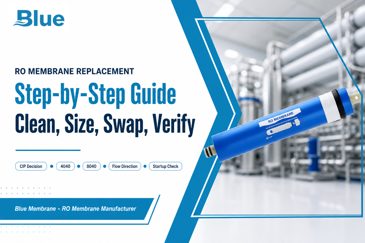
This RO Membrane Replacement Guide is a condition-based, evidence-driven walkthrough covering when to replace a reverse osmosis membrane, how to tell fouling from scaling, and the full industrial and residential swap procedure used to protect water quality.
Quick Specs
| Common industrial housing sizes | 4040 and 8040 spiral-wound |
| Performance test basis | ASTM D4516 (standardizes how RO/NF performance data is tested and reported; manufacturer-reported flow tolerance commonly ±15%) |
| Residential certification frame | NSF/ANSI 58 (POU systems; 50–1,600 GPD and dimensional tolerance are manufacturer/product-datasheet figures, not standard-mandated values) |
| Replace-trigger flow decline | Normalized permeate flow down >10% and not recovering after CIP |
| Typical element life range | 2–10+ years, application-dependent |
Most reverse osmosis membrane replacement guides give you a single number, replace every two years, and stop there. That number is a rough average, not an engineering answer, and it leads plants to pull elements that still have years of service left while other elements fail early because nobody watched the flow trend. This guide walks through the measurable signals that actually tell you it’s time, how to tell fouling from scaling before you commit to a fix, a repeatable clean-vs-replace test, real cost drivers, how industrial spiral-wound elements differ from residential cartridges, how to size and cross-reference a replacement, and the full step-by-step guide to the swap procedure, including the early failure modes engineers run into after a replacement, in one place.
Reverse osmosis membrane replacement means swapping a fouled or degraded RO element once cleaning-in-place (CIP) no longer restores normalized permeate flow or salt rejection. The reliable trigger is a sustained flow decline of more than 10%, rising salt passage, or physical damage — not a fixed calendar date.
Key Points
- Elements can run more than 10 years in low-fouling service; a rigid replacement calendar often pulls membranes early that still have usable life left.
- Cleaning can’t always bring an element back; once physical damage (tears, delamination) has occurred, no CIP recipe restores rejection.
- A rising salt-passage reading is sometimes an O-ring problem, not a membrane problem; check the seal before condemning the element.
- Industrial spiral-wound replacement and residential POU cartridge replacement are governed by different tolerance standards and shouldn’t follow the same procedure.
6 Signs Your RO Membrane Needs Replacing (Not Just Cleaning)
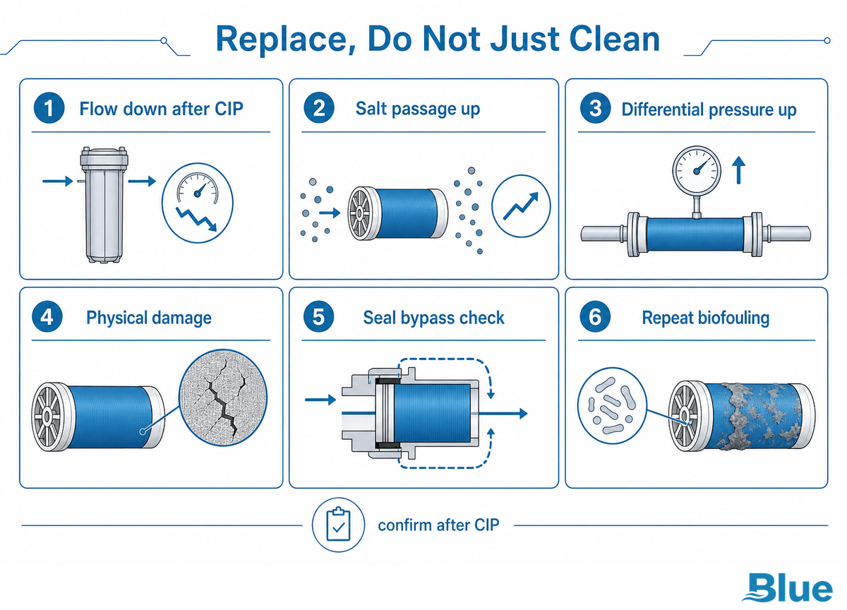
An RO membrane needs replacing rather than cleaning when normalized permeate flow drops more than 10–15% and stays down after a CIP cycle, salt passage climbs 5–10% or more and doesn’t recover, differential pressure rises 10–15% without falling back after cleaning, or physical damage has already begun to damage the membrane, such as a torn or delaminated skin. These four measurable signals, not simply how many years the element has been in service, tell you it’s time to replace rather than clean, and timely replacement at that point keeps higher total dissolved solids levels out of the product water downstream.
-10%normalized permeate flow, CIP trigger
+5–10%salt passage rise, CIP trigger
+10–15%differential pressure rise, CIP trigger
These thresholds come from standard industrial RO KPI practice and mark when to clean, not automatically when to replace; replacement is warranted only when the same signal persists after a proper CIP cycle. Note also that TDS and salt-rejection percentage are performance-screening signals for membrane condition, not proof that a specific regulated contaminant is being removed; use them alongside your facility’s own water-quality testing program rather than as a stand-alone compliance figure. These same metrics show up among the key performance indicators tracked in standard reverse osmosis operation, alongside Silt Density Index and the Pressure Drop Coefficient, and reading them as one integrated dashboard rather than isolated numbers is what actually catches degradation early. Evaluating these same signals up front, rather than only after a system is built and running, is the same underlying goal behind documented membrane-technology performance evaluation methodology.
| Signal | What it looks like | Replace-trigger |
|---|---|---|
| Flow decline after CIP | Normalized permeate flow won’t return to baseline | >10–15% below baseline, unrecovered |
| Rising salt passage after CIP | Product water TDS climbs and stays up | >5–10% above baseline, unrecovered |
| Persistent differential pressure | ΔP stays elevated across a vessel bank after cleaning | >10–15% above baseline |
| Physical membrane damage | Torn or delaminated skin, telescoping, cracked end caps | Immediate — no CIP recipe restores torn membrane |
| Localized salt-passage spike | One vessel/element reads high while neighbors are normal | Check O-ring/seal first — often a seal fix, not a membrane fault |
| Sustained biological/organic fouling | Repeat CIP cycles needed within weeks of each other | Element replacement once cleaning frequency becomes uneconomical |
How Do You Know If Your RO Membrane Is Bad?
You know an RO membrane is bad, not just dirty, when a documented CIP cycle fails to bring normalized permeate flow and salt rejection back to within roughly 10% of their baseline readings. A membrane that responds well to cleaning is in a cleanable fouling or scaling condition.
A membrane that stays degraded after a correctly executed cleaning has crossed into physical or chemical degradation territory: the polyamide skin itself has been compacted, oxidized, or torn, and no further CIP cycle will change that. Before condemning the element, rule out a damaged O-ring or a reversed flow-direction installation, since both can mimic a failing membrane by allowing raw feedwater to bypass the rejection layer and read as elevated salt passage on an otherwise healthy element.
What’s Actually Fouling or Scaling the Membrane, and Why It Changes Your Timeline
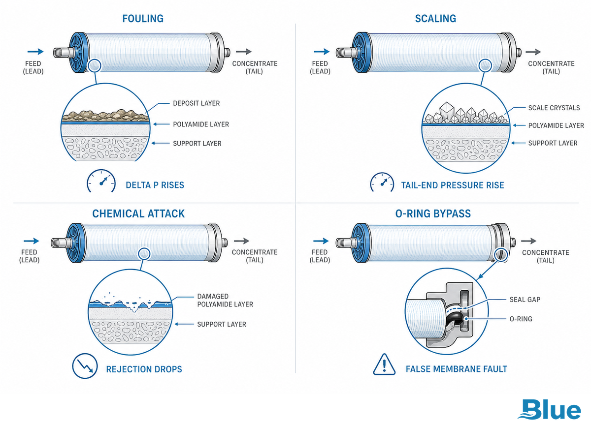
Fouling and scaling are different failure mechanisms with different timelines and different fixes, and treating them as the same problem is one of the most common misdiagnoses in RO operation. Fouling — particulate, colloidal, organic, or biological material building up on the membrane surface — usually shows up as rising differential pressure at the front of the array and typically responds to CIP.
Scaling — carbonate, sulfate, or silica precipitating out of solution as it concentrates through the vessel bank — shows up as rising pressure drop toward the tail (concentrate) end and is harder to reverse once it crystallizes on the membrane surface.
| Type | Root cause | ΔP signature | CIP-reversible? |
|---|---|---|---|
| Particulate/colloidal fouling | Suspended solids, poor pretreatment filtration | Rises at lead (first-stage) elements | Usually yes |
| Biological fouling | Microbial growth on membrane/spacer surface | Rises across the array, worsens between CIPs | Often, if caught early |
| Carbonate/sulfate scaling | Concentrate-side supersaturation, under-dosed antiscalant | Rises at tail (concentrate-end) elements | Partially — depends on crystal maturity |
| Silica scaling | Dissolved silica above roughly 40 mg/L at high recovery | Rises at concentrate-end elements | Difficult — often needs specialized cleaning or replacement |
| Chemical/oxidative degradation | Chlorine/chloramine exposure, cleaning-chemical misuse, pH excursions | No consistent ΔP pattern — rejection drops without fouling signature | No — irreversible, replacement only |
| Iron/manganese fouling | Oxidized iron or manganese precipitating out of the feedwater onto the membrane surface | Rises sharply at lead elements; reddish-brown deposit visible on inspection | Usually yes, with a low-pH citric-acid cleaning step |
| Colloidal/organic fouling (high SDI feed) | Inadequate pretreatment letting a high Silt Density Index feed through to the array | Gradual ΔP climb concentrated at the lead elements | Usually yes if caught before it compacts |
| Mechanical telescoping/damage | Hydraulic shock during repressurization or a too-fast startup ramp | No consistent ΔP pattern — visible physical deformation on element inspection | No — mechanical repair or replacement only |
| O-ring/seal bypass (false-positive fault) | Worn, dry, or improperly seated O-ring letting raw feedwater bypass the rejection layer | Elevated salt passage with no matching ΔP change | No — reseal or replace the O-ring, not the membrane |
That fifth row matters: not every early failure is a deposit problem. Oxidative attack from excess chlorine or chloramine, misused cleaning chemicals, or repeated pH excursions degrades the polyamide layer directly, and it won’t show up as a fouling or scaling pattern at all; rejection simply drops. Because it’s a chemical failure of the membrane itself rather than something sitting on the surface, no CIP recipe reverses it, which is why distinguishing it from recoverable fouling or scaling early changes whether you reach for a cleaning skid or a replacement element. When the diagnostic table above doesn’t explain a persistent problem, the next step is the fouling-resistant RO elements route rather than another cleaning attempt.
Membrane life also shifts by application, not just by water chemistry: municipal drinking-water systems commonly get 5–7 years from an element, industrial ultrapure-water duty typically sees 3–5 years, wastewater-reuse service runs 2–4 years, and high-fouling industrial feed can drop to 1–3 years even with a competent maintenance program — put simply, an RO membrane typically lasts somewhere in that range depending on duty rather than a fixed number of years, and tracking flow trend data over the life of your RO system is what lets you catch the transition from fouled to degraded early. A 2022 International Desalination Association operational review is worth flagging here for the same reason as the diagnostic table above: it found that most early membrane failures trace back to inadequate pretreatment or deferred maintenance rather than a defective element, which is another reason to run the fouling/scaling/degradation diagnosis before assuming a membrane simply wore out on schedule. Predicting which failure mode a given feedwater will trigger without pulling elements for inspection is the same underlying challenge addressed by documented alternatives to full pilot-plant studies for membrane technology evaluation — evaluating fouling and scaling potential before a system is fully built out, rather than only diagnosing it after the fact.
Clean It or Replace It? The Flow-Recovery Test
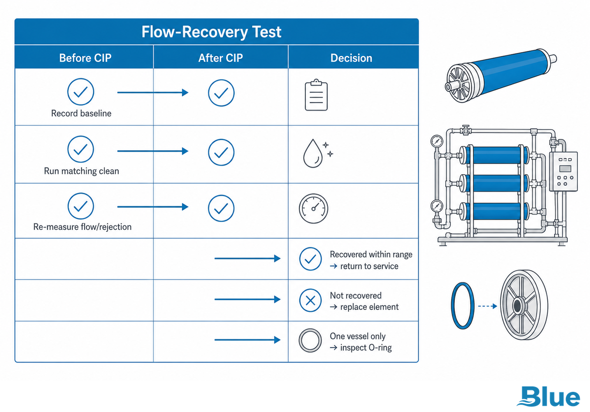
The Flow-Recovery Test answers the clean-or-replace question with one post-CIP measurement instead of a guess: run a documented cleaning cycle, then check whether normalized permeate flow and salt rejection return to within roughly 10–15% of baseline. If they do, keep cleaning on the standard schedule. If they don’t recover after a properly executed CIP, the element has moved from “dirty” to “degraded,” and further cleaning cycles mostly add chemical cost and downtime without buying back performance.
The Flow-Recovery Test — Decision Steps
- Record baseline normalized permeate flow, salt rejection, and differential pressure before cleaning.
- Run the appropriate CIP recipe for the fouling/scaling type identified in the diagnostic table above.
- Re-measure the same three parameters under matched temperature and pressure conditions.
- If flow and rejection are within ~10–15% of baseline: return to service, log the cycle, continue routine CIP schedule.
- If flow or rejection remain more than 10–15% below baseline after cleaning: schedule replacement rather than a repeat CIP.
- If only one element in a vessel read low while neighbors test normal: inspect the O-ring and seating before condemning the element.
“Reliance on simple time-based limits may result in replacing the membrane prematurely, elements have been known to last more than ten years. One size does not always fit all; your challenges are unique and your solutions should be too.”
Wes Byrne, Industry Consultant, writing on RO membrane replacement timing
This is why a fixed calendar and a condition-based test can disagree. A rigid two-year replacement schedule is easy to budget for, but it pulls elements that still test within spec while allowing a badly fouled system running on the same calendar to limp along underperforming until its scheduled date. Cleaning also has a limit worth stating plainly: it can’t always bring an element back. For older or heavily fouled membranes, cleaning removes what has accumulated on the surface, it can’t undo physical damage such as a torn or oxidized membrane, and it’s not always possible to recover the full baseline performance once aggressive cleaning chemistry has itself begun to attack the membrane surface. One narrower category of chemical treatment exists in the water-treatment industry, patented specifically to restore rejection rate on an already-degraded membrane, but it addresses a different degradation profile than routine CIP and isn’t a substitute for the Flow-Recovery Test above.
Key takeaway
If normalized permeate flow and salt rejection don’t recover to within roughly 10–15% of baseline after a proper CIP cycle, replace the element — a calendar date alone is not a reliable trigger.
RO Membrane Replacement Cost: What Actually Drives the Price
RO membrane replacement cost varies widely because it’s driven by element grade, housing size, and system scale rather than one flat number. An industrial brackish-water element commonly runs in the low hundreds of dollars per unit, and a multi-vessel commercial reverse osmosis filtration system’s per-cycle cost stacks element price against labor, downtime, and disposal. Quoting a single “average membrane replacement cost” figure without those drivers is one of the more common gaps in existing buying guides.
| Cost driver | What changes the number |
|---|---|
| Element grade/series | Industrial 8040 brackish elements are reported at roughly $200–450 per element depending on rejection grade and OEM vs. compatible sourcing — confirm against a current supplier quote for your specific series |
| System scale | A single residential cartridge vs. a multi-vessel industrial bank changes total spend by an order of magnitude |
| Labor & downtime | Vessel access, isolation, and requalification time add to element cost, especially on continuous-run lines |
| Operating cost basis | Reported industrial RO operating costs run roughly $0.20–0.40 per m³ of permeate, covering energy plus periodic element replacement — definitions of what’s included (energy only vs. energy+chemicals+labor) vary by source, so use this as a planning range rather than a fixed budget line |
| Cleaning vs. replace cadence | More frequent CIP cycles can defer replacement cost short-term but add chemical and labor spend over the element’s life |
Two levers matter more than the sticker price on a single element: how many vessels have to come offline at once, and whether the replacement is planned around a maintenance window or forced by an unplanned failure. Planned, condition-based replacement using the Flow-Recovery Test above avoids the higher cost of emergency downtime and lets a facility batch multiple vessel change-outs into one planned outage, turning what could be an emergency membrane change into routine, budgeted maintenance. Public-sector cost modeling for RO/NF systems, such as the EPA’s RO/NF Work Breakdown Structure cost model documentation, breaks total cost into comparable categories: capital, labor, energy, and chemicals. That is the same reason the driver table above separates element price from labor, downtime, and operating cost instead of quoting one average figure.
Industrial vs. Residential RO Membrane Replacement: Why One Guide Doesn’t Fit Both
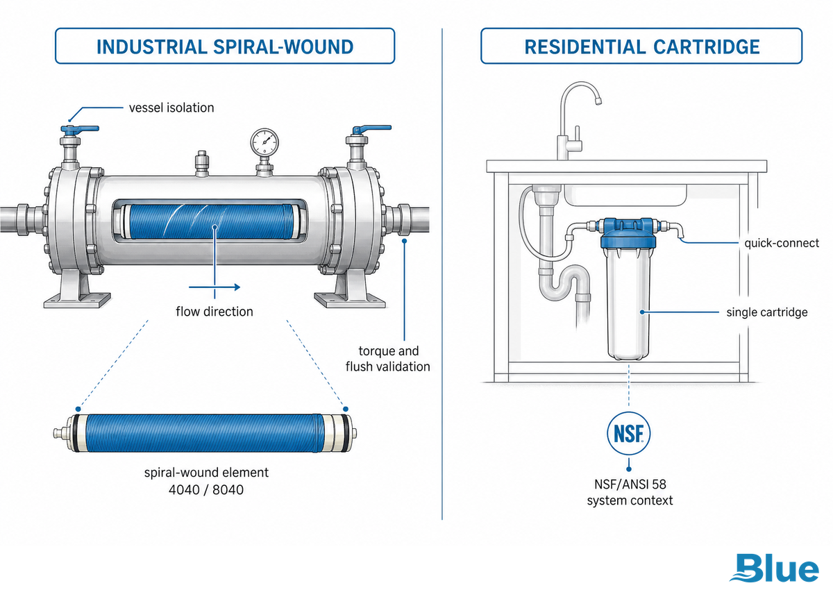
Industrial spiral-wound RO membrane replacement and residential point-of-use (POU) cartridge replacement are governed by different tolerance standards, different housing formats, and different procedures, so a residential how-to guide will not transfer cleanly to a commercial or industrial system. Residential POU elements are built and certified against NSF/ANSI 58, which governs residential drinking-water treatment systems specifically; industrial spiral-wound elements are performance-tested under ASTM D4516, which standardizes how RO/NF performance data is measured and reported rather than setting a universal tolerance figure itself. Treating the two as interchangeable is where a lot of buying mistakes start.
| Attribute | Residential POU cartridge | Industrial spiral-wound element |
|---|---|---|
| Governing standard | NSF/ANSI 58 (residential RO drinking-water systems — certifies system performance/materials, does not itself fix cartridge dimensions) | ASTM D4516 (standardizes how RO/NF performance data is tested and reported, not a tolerance mandate) |
| Format & housing | Small cartridge, quick-connect fittings; typical products span roughly 50–1,600 GPD (product-market range, not an NSF/ANSI 58 requirement) | 4040/8040 spiral-wound in pressure-vessel housings |
| Dimensional/flow tolerance | Manufacturer datasheet tolerance on element geometry (varies by OEM; consult the specific product datasheet rather than the standard) | Manufacturer-reported flow tolerance commonly around ±15%, tested on an ASTM D4516 basis |
| Tools/procedure complexity | Basic hand tools, single-cartridge swap | Vessel isolation, multi-element pull, torque specs, flush validation |
| Typical flow range (product market, not standard-mandated) | Roughly 50–1,600 GPD across common residential product lines | Thousands of GPD per vessel bank, scaling to full plant flow |
NSF/ANSI 58 is a residential POU certification framework, worth noting explicitly, because it should not be read as a general authority for industrial replacement-element interchangeability. If a residential system needs to preserve a specific contaminant-reduction certification after replacement, the replacement cartridge needs to match the certified configuration, not just fit the housing. For a system built to the residential POU standard, start from residential RO elements rather than an industrial spiral-wound catalog.
Choosing the Right Replacement Element: Specs, Sizing & Cross-Reference
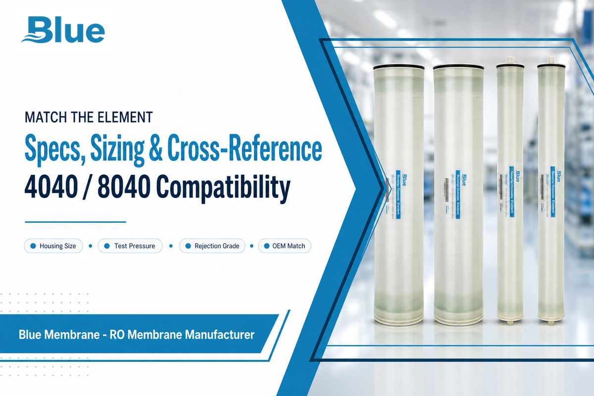
Choosing the right replacement element means matching housing size, test-pressure rating, and rejection grade to your original element’s datasheet, then cross-referencing that datasheet against equivalent brands rather than assuming any element that physically fit the housing will perform the same. Two elements can share a 4040 or 8040 housing size and still differ meaningfully in rejection percentage, permeate flow, and maximum feed TDS. Get the housing-grade-flow match wrong and you’ll see a replacement that fits but underperforms — whether you replace RO elements on an industrial train or replace your reverse osmosis cartridge under a sink.
| Series | Type | Test psi | Rejection % | OEM cross-reference |
|---|---|---|---|---|
| MB-C1 | Low-Pressure/ULP, energy-tuned | 150 | 99.5–99.6 | DuPont Eco Pro-400, Hydranautics ESPA2-LD, Toray TMG20-400 |
| MB-C2 | Low-Pressure/ULP, higher flow | 225 | 99.5–99.6 | DuPont BW30HRLE-440, Hydranautics ESPA1-LD, Toray TM720D-400 |
| MB-Z1 | Brackish water, standard rejection | 225 | Standard high-rejection duty | DuPont BW30-400/34, Hydranautics CPA3, Toray TM720-400 |
| MB-Z2 | Fouling-resistant (max feed TDS 10,000 ppm) | 225 (max 600) | Hydrophilic polyamide surface | DuPont BW30FR-400/34, Hydranautics LFC3-LD, Toray TML20-400 |
| MB-H1 | Seawater, maximum rejection | 800 (max 1,200) | 99.8/99.7 stable/min | DuPont SW30HRLE-400, Hydranautics SWC5-LD, Toray TM820C-400 |
| MB-H2 | Seawater, energy-efficient (+20% permeate vs. H1) | 800 (max 1,200) | 99.7/99.6 stable/min | Comparable seawater-grade energy-efficient elements |
Under an identical 800 psi / 32,000 ppm NaCl / 25°C test basis, the MB-H1 seawater element delivers 7,500 GPD on an 8040 housing at 99.8%/99.7% stable/minimum rejection, while the MB-H2 trades a small amount of rejection margin (99.7%/99.6%) for roughly 20% more permeate at 9,000 GPD, a real trade-off worth checking against your recovery and energy targets before defaulting to the highest-rejection option. Physical compatibility with a housing isn’t the same as preserving your original system’s certified performance: a third-party element that fits the vessel may still fall outside your process’s feed-TDS or rejection requirements, and if the original system carries a manufacturer warranty or a certified contaminant-reduction claim, a non-approved substitute can void that certification even though it seats and pressurizes normally. Rejection-rate performance also isn’t fixed for life once an element is installed: patented chemical treatments exist specifically to restore rejection rate on a membrane already showing decline, though that’s a narrower fix than choosing the correct spec upfront and shouldn’t be assumed as a substitute for correct initial sizing.
RFQ checklist — copy these into your quote request:
| Parameter | Recommended range | Why it matters | How to verify |
|---|---|---|---|
| Housing size | 4040 or 8040 | Wrong size means the element won’t seat | Measure existing vessel or check nameplate |
| Test pressure basis | 150–800 psi depending on series | Mismatched test basis skews expected flow/rejection | Request datasheet test conditions |
| Salt rejection grade | 99.5–99.8% depending on series | Determines whether product water meets your process TDS target | Ask for stable and minimum rejection, not just stable |
| Max feed TDS | Up to 10,000 ppm for fouling-resistant series | Exceeding it accelerates scaling/fouling | Compare against your feedwater analysis |
| Governing standard | ASTM D4516 (industrial) or NSF/ANSI 58 (residential POU) | Confirms the element was tested/certified for your application class | Request the test certificate |
| Certification/warranty preservation | OEM-approved equivalent or explicit compatibility statement | Non-approved substitutes can void warranty or certified contaminant claims | Get written cross-reference confirmation from the supplier |
Once you’ve got the housing size, test-pressure basis, and rejection grade confirmed, the fastest path to an accurate quote is the cross-reference chart, which maps Blue Membrane’s RO membrane elements against the major OEM lines shown in the table above — the table lists equivalent DuPont FilmTec, Hydranautics UF membrane, and Toray RO element product codes side by side so you can cross-check a replacement without guessing at fit.
How to Replace an RO Membrane: The 12-Step Membrane Swap Sequence
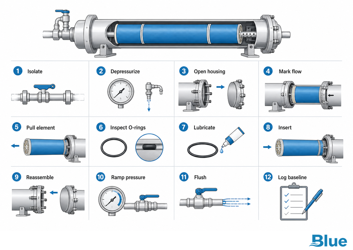
The RO membrane replacement procedure safely follows a fixed sequence: isolate the pressure vessel, relieve pressure, open the housing, note flow direction before you pull out the old membrane, install the new membrane and lubricate its O-rings, remove air from the housing as you reconnect and pressurize gradually, then flush before returning the system to service. Skipping the flow-direction check or reusing a dry O-ring are the two mistakes that cause the most callbacks on an otherwise correct swap.
💡 Pro Tip
Mark the feed-end of the old element with tape before you pull it. Spiral-wound elements only work in one flow direction, and a reversed installation is one of the most common — and most avoidable — causes of an immediate post-replacement salt-passage spike.
- Isolate the vessel — close feed, permeate, and concentrate valves for the vessel bank being serviced.
- Relieve system pressure — bleed pressure to zero before opening any housing end cap.
- Open the housing — remove the membrane housing cap’s retaining ring or thrust collar per the housing manufacturer’s torque spec.
- Mark flow direction — tape or note the feed-end of the old element before removal to confirm correct orientation on the new one.
- Pull the old element — use an element puller or extraction rod; avoid twisting, which can damage the fiberglass shell.
- Inspect the housing and O-rings — check interconnectors and housing O-rings for nicks, flat spots, or dry rubber; replace any that show wear.
- Lubricate new O-rings — use a compatible, non-petroleum lubricant on all seal surfaces before insertion.
- Insert the new element — orient the feed end to match the marked direction from step 4 and seat the new membrane into the housing fully against the interconnector.
- Reassemble the housing — reinstall the end cap and retaining hardware to the specified torque.
- Repressurize gradually — bring the vessel back to operating pressure slowly to avoid a hydraulic shock that can telescope the new element.
- Flush before production — run the system to drain for the manufacturer’s specified flush volume and time to clear preservative solution and loose particulate.
- Verify performance — log baseline normalized permeate flow, salt rejection, and differential pressure on the new element for future Flow-Recovery Test comparisons.
What Tools Do I Need to Change Reverse Osmosis Filters?
Changing reverse osmosis membranes and their upstream pre-filters typically calls for an adjustable or torque-specified wrench for the housing end cap, an element puller or extraction rod for spiral-wound elements in industrial vessels, a non-petroleum O-ring lubricant, a pressure gauge to confirm the vessel has been fully depressurized, and a clean surface or tray to keep the new filters, O-rings, and hardware organized during reassembly of the RO membrane housing.
Residential POU water filter swaps need far less, usually just a housing wrench and the replacement cartridge, while multi-vessel industrial replacements benefit from a documented torque spec and a second technician to support the element during extraction.
What Should I Do After Replacing My RO Filters — Is There a Flushing Process?
Yes, every new RO element ships with a preservative solution that must be flushed out before the system returns to production, and skipping this step is a common cause of off-taste or odor immediately after replacement. Run the system to drain, not to product water, for the manufacturer’s specified flush duration and volume, then verify permeate quality against baseline and check the housing end caps for any leak before routing water to the process or storage tank.
How Is a Residential Under-Sink Membrane Swap Different from the Industrial Steps Above?
A residential under-sink swap skips most of the 12-step vessel sequence: shut off the feed-water valve, open the RO faucet to bleed pressure out of the RO water side, then remove the membrane housing by pressing the collar to release the quick-connect tubing. A small pair of pliers can help ease a stiff collar loose, but squeezing the tubing itself with pliers is what actually splits the push-fit line, so use them on the collar only.
Pull the old cartridge straight out, seat the new one, reconnect the tubing, and restore feed pressure to resume reverse osmosis water production. Before drinking the clean water, flush the system for the first 15–20 minutes of production to clear the storage solution the element ships in. If flow comes out slow afterward, check the tubing for a kink or a clog at the fitting first; on a fresh residential install, a pinched line is a far more common culprit than a defective membrane. This lighter procedure matches how EPA’s WaterSense program describes point-of-use RO systems generally, small, quick-connect units built for simple homeowner service rather than the vessel-isolation and torque-spec discipline the industrial 12-step sequence above requires.
After Replacement: Startup, Flushing & Troubleshooting Early Problems
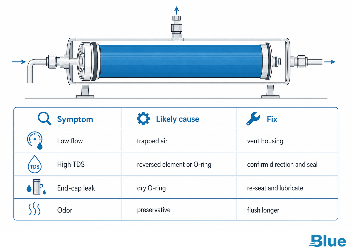
Startup after RO membrane replacement means running a controlled flush, gradually ramping to operating pressure, and confirming permeate flow and TDS match the new element’s datasheet before handing the system back to production. Most early problems trace back to a skipped flush, a reversed element, or a seal that wasn’t lubricated during the swap.
| Symptom | Likely root cause | Fix |
|---|---|---|
| Low permeate flow | Incomplete pressurization ramp or trapped air | Re-check pressure ramp-up procedure; vent air from housing |
| High TDS in product water | Reversed element, damaged O-ring, or unfinished flush | Confirm flow direction; inspect O-ring; extend flush cycle |
| Leak at housing end cap | Under-torqued retaining hardware or unlubricated O-ring | Re-torque to spec; re-lubricate and reseat O-ring |
| Off-taste or odor | Residual preservative solution not fully flushed | Run extended flush to drain before returning to product water |
Mixing new and old elements in the same vessel bank is worth flagging separately: uneven element condition across a bank distributes flow unevenly, so a bank that gets a partial replacement should be rebalanced and its baseline re-logged rather than assumed to perform like a uniformly new bank. When a symptom doesn’t clear after checking flow direction, seals, and flush completeness, the next diagnostic step is a full autopsy-style inspection of the pulled element rather than repeated swaps. If a membrane in your RO system keeps failing the Flow-Recovery Test and the membrane is not replaced, the same startup problems documented above tend to resurface within weeks. Logging that new-element baseline is the same discipline behind the documented performance-indicator tracking used in reverse osmosis operation, normalized permeate flow, percent salt rejection, differential pressure, Silt Density Index, and the Pressure Drop Coefficient, so the numbers recorded at startup become the reference point every future Flow-Recovery Test compares against. It’s the same startup-baseline logic behind documented membrane-technology evaluation methodology: a clean reference dataset recorded at day one is what every later performance comparison depends on.
Integration & Utility Requirements for Industrial RO Replacement Programs
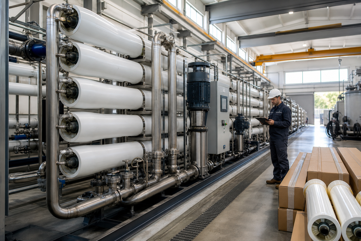
Planning a membrane replacement program at industrial scale means checklisting feed-pump capacity, spare-housing footprint, downtime windows, and control-system compatibility before scheduling a multi-vessel swap. Treating replacement as a one-element-at-a-time task instead of a planned utility event is what turns a routine change-out into unplanned downtime. The goal across all of this planning is simple: keep your reverse osmosis system producing high-quality water and maintain water quality without an unplanned outage.
| Utility/parameter | Typical requirement | Why it matters |
|---|---|---|
| Feed-pump capacity | Rated for the highest test-pressure series in use (up to 1,200 psi, seawater lines) | Undersized pumps can’t reach the new element’s rated operating pressure |
| Spare-housing footprint | Space for isolated bank servicing without taking the full train offline | Lets replacement happen without a full plant shutdown |
| Downtime window | Scheduled around production, not reactive to failure | Planned change-outs avoid the higher cost of emergency replacement |
| Control/interlock compatibility | PLC setpoints updated to the new element’s flow/pressure baseline | Stale setpoints trigger false alarms or mask real degradation |
These planning requirements apply whether the system runs on brackish water RO systems at the lower end of the pressure range or seawater RO systems running near the top of it; the higher the test pressure, the less margin there’s for an undersized feed pump or a stale control setpoint to go unnoticed. One additional planning note worth carrying forward: if any part of a facility’s water program touches a regulated-contaminant certification, PFAS reduction claims are the current example, given EPA’s 2024 PFAS National Primary Drinking Water Regulation and the related implementation activity still working through the system, replacement elements need to match the certified configuration, not just the housing and pressure rating. Check the certifying body’s (e.g., NSF/WQA) product listing before replacement, since swapping in a non-listed element is what actually puts a certified contaminant-reduction claim at risk, not the replacement event itself. That planning logic mirrors the same categories used in EPA’s RO/NF cost-modeling documentation: capital, labor, energy, and chemicals treated as separate line items rather than folded into one number, exactly the breakdown a multi-vessel change-out program needs to budget correctly.
Frequently Asked Questions
Q: How often should you replace your RO membrane?
There’s no single correct interval for reverse osmosis membrane replacement — service life ranges from two to more than ten years, and the decision should follow condition-based signals like flow and rejection loss, not a fixed calendar date.
Industrial elements can run anywhere from two to more than ten years depending on feedwater quality, pretreatment, and duty cycle. Rather than a fixed replacement date, use the Flow-Recovery Test above: if normalized permeate flow and salt rejection don’t return to within roughly 10–15% of baseline after a proper CIP cycle, replace the element regardless of how long it’s been in service.
Q: Can I replace the RO membrane myself?
Residential POU cartridge swaps are commonly done in-house with basic tools, while industrial spiral-wound replacement is more demanding, involving pressure isolation and torque-specified reassembly, and often benefits from trained maintenance technicians or the element supplier’s field service team.
A residential cartridge change generally needs only a housing wrench and the correct replacement part. Industrial multi-vessel replacement involves pressure isolation, torque-specified reassembly, flow-direction verification, and a documented flush and startup procedure — mistakes at any of those steps (particularly a reversed element or a dry O-ring) are the leading causes of post-replacement callbacks, so many facilities use trained maintenance staff or the element supplier’s field team for industrial swaps.
Q: How much does it cost to replace a RO membrane?
Industrial 8040 elements commonly run in the low hundreds of dollars per element, with total cost driven more by labor and downtime than the element price alone.
Industry-reported figures put industrial 8040 brackish-water element pricing at roughly $200–450 per element and operating costs for industrial RO systems around $0.20–0.40 per m³ of permeate — order-of-magnitude reference points, not a quote, since neither range specifies feedwater salinity, energy price, or plant scale. The bigger cost swing comes from labor, downtime, and whether the replacement is planned or reactive — see the cost-driver table above for the full breakdown, and request a facility-specific quote before budgeting.
Q: How do I know if my RO membrane is bad?
A membrane is bad, not just dirty, if normalized permeate flow and salt rejection don’t recover to within roughly 10 to 15 percent of baseline after a properly documented cleaning-in-place cycle.
Check normalized permeate flow, salt passage, and differential pressure against baseline after a proper cleaning cycle — see the six-signal table and Flow-Recovery Test above for the full diagnostic sequence.
Q: What happens if I don’t replace my RO membrane on time?
Product water quality and flow both continue to decline as a degraded membrane ages further past its usable service window, and downstream equipment can be exposed to elevated TDS and rising salt passage that a timely replacement would have prevented.
Running past the point of CIP recovery raises salt passage into product water, which can affect downstream process quality or equipment.
Q: Are RO membranes expensive compared to cleaning?
Cleaning is cheaper per cycle, but repeated cleaning on a degraded element that no longer recovers flow and rejection eventually costs more in chemicals and downtime than simply installing a new replacement element.
One CIP cycle costs less than a new element, but once flow and rejection stop recovering, continued cleaning adds chemical and downtime cost without restoring performance.
Q: How do I know which replacement element is compatible with my housing?
Match housing size, test-pressure basis, and rejection grade against your original element’s datasheet, then confirm fit and performance equivalence with an OEM cross-reference chart before ordering, since physical fit alone doesn’t guarantee the same rejection or flow rating.
Use the RFQ checklist and cross-reference table above; physical fit alone doesn’t guarantee equivalent performance or preserve an existing warranty or certification.
Need help matching a replacement element to your existing housing and spec?
Why We Write This
Blue Membrane manufactures spiral-wound RO elements across six industrial series and residential NSF/ANSI 58 lines, and the replacement guidance above reflects the same tolerance data, test-pressure basis, and OEM cross-reference information we publish on our own product pages, not a generic replacement checklist. Reviewed by the Blue Membrane technical team.
References & Sources
- Point-of-Use Reverse Osmosis Systems — U.S. EPA WaterSense
- RO/NF Work Breakdown Structure Cost Model Documentation — U.S. EPA
- ASTM D4516-19a, Standard Practice for Standardizing Reverse Osmosis Performance Data — ASTM International
- Alternatives to Pilot Plant Studies for Membrane Technologies — Texas Water Development Board
- NSF/ANSI 58: Reverse Osmosis Drinking Water Treatment Systems — NSF
- 5 Key Performance Indicators in Reverse Osmosis Operation — Water Technology
- US10046280B2, Method for Improving Rejection Rate of Reverse Osmosis Membrane — Google Patents / Kurita Water Industries
Related Articles
- What Is an RO Membrane? — how an RO membrane works and how it’s built
- RO vs. Nanofiltration — how NF and RO membranes actually differ
- RO Membrane Elements — full industrial product line
- Fouling-Resistant RO Elements — MB-Z2 series for high-fouling feedwater
- Residential RO Elements — NSF/ANSI 58 certified POU line
- talk to our engineering team — for element sizing and cross-reference questions