Get in touch with Blue Membrane Company

Types of RO Membranes: Material, Feedwater and Duty

Industrial water treatment guide
The phrase types of RO membranes encodes numerous decisions. For example, a purchaser may compare thin-film composites to cellulose acetates, brackish water to seawater, low pressure to fouling-resistant designs, or 4040 to 8040 configurations. These labels denote various axes. The purpose of this manual is to link the axes so that an engineer can shortlist a membrane without taking the headline rejection number as an absolute specification.
These types of reverse osmosis membranes appear in the context of wider membrane technology and commercial RO membranes used in RO systems. The reverse osmosis process moves water molecules through a selective layer, so chemistry and application must be integrated in membrane selection. For service of drinking water and pure water, the target quality should be provided next to the feed water analysis. A single type of membrane rarely fits all clean water duties.
Common thin film composite membrane designs use polyamide membranes to support membrane performance. TFC membranes and CA membranes are other options. If, for example, cellulose acetate is being considered and chlorine exposure or legacy water treatment dictates a change in selection, then the fouling limits and dissolved-solids removal limits remain to be defined from the current data sheet.
For seawater RO membranes, energy and rejection are principal considerations. The best RO membrane, therefore, starts with the water source and the better water quality, and checks the operating envelope.
Nanofiltration membranes and RO technology intersect at the boundary of hardness and dissolved solids removal. A buyer should consider purified water, membrane efficiency and the intended water purification system prior to selecting a family.
Thin-film composite membranes are made for various duty envelopes, and these membranes are designed within the limits that membrane manufacturers list in their current data sheets. Compare advancements in membrane technology only after the operating conditions are equivalent.
High-quality RO membranes still require a semi-permeable membrane, a clean pretreatment and a reasonable recovery target. Hence, residential RO and industrial trains shouldn’t share the same selection rule.
Measure water flux and salt rejection together; a drop in either can indicate membrane degradation or a change in feedwater. NF membranes and RO membranes work differently, even if the equipment looks similar.
The available membrane options consist of a few RO membrane series, and each series has its own membrane integrity and notes on cleaning and replacement. Match the notes with your specific water treatment needs.
RO membranes for desalination are designed for a complete process; therefore, the goal is clean and safe water rather than a catalog number. The final analysis should state the test water, pressure, and recovery.
What are the main types of RO membranes?
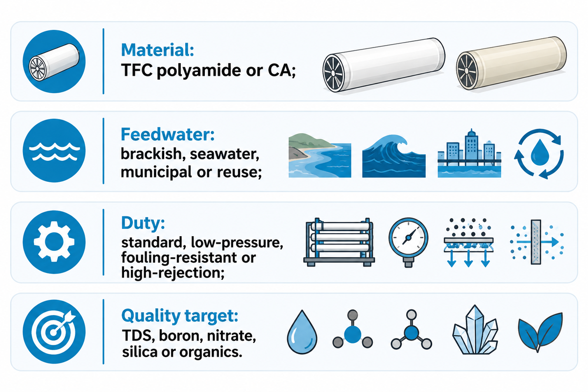
Reverse osmosis elements are best classified by four parameters: membrane material, class of feedwater, duty of operation, and the level of target for quality of permeate. For the classification context, see the U.S. Environmental Protection Agency membrane reference. This framework links the material choice to the feedwater and duty decisions that follow. Nanofiltration, in general, rejects divalent ions more strongly compared to monovalent salts. It’s placed next to RO, and not within any RO category. Some other elements include thin-film composite (TFC) polyamide, cellulose acetate (CA), brackish-water RO (BWRO), seawater RO (SWRO), low-pressure or ultra-low-pressure RO, and fouling resistant RO elements.
The Texas Water Development Board states that RO and NF are pressure-driven membrane processes and that RO membranes are typically made of cellulose acetate or composite materials. A technical review by Kurita also groups brackish, SW and NF elements by feedwater and duty. The important point here is that the material doesn’t reveal the correct operating pressure, recovery or pretreatment.
| Axis | Examples | Question it answers |
|---|---|---|
| Material | TFC polyamide, CA | What chemistry and cleaning window can the active layer tolerate? |
| Feedwater | Brackish, seawater, municipal, reuse | What osmotic pressure, fouling load and recovery are expected? |
| Duty | Standard, low-pressure, fouling-resistant, high-rejection | Which trade-off matters: energy, flux, rejection or stability? |
| Quality target | TDS, boron, nitrate, silica, organics | Which contaminants and rules define acceptable permeate? |
The Three-Axis RO Fit Map: Material, Feedwater and Duty
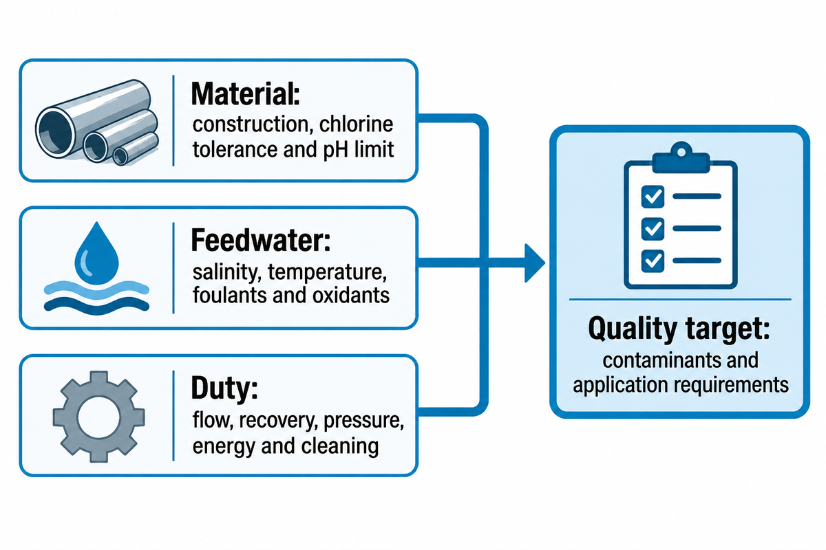
A good first approximation is to identify the active material, feedwater class, operating duty, and the target water quality. The Texas Water Development Board membrane fundamentals provides the supporting process context. This is critical because a membrane can have excellent salt rejection but require a different treatment for boron, nitrate, volatile organic compounds, or an on-site discharge limit.
- Identify the active material, support construction, chlorine tolerance and the pH limit expressed by the supplier.
- Identify feedwater constituents including total dissolved solids, temperature, hardness, silica, SDI, oil, biology, and any oxidant residual.
- Define the target permeate flow, recovery, pressure limit, energy limit and frequency of cleaning for the process duty.
- Provide the contaminants, and the applicable potable, process or reuse requirements, as the quality targets.
Don’t simplify to one “best membrane” score. There are trade-offs in Kurita’s system-design guide, including feedwater source, desired recovery, water quality, and energy requirements, that affect element selection. That’s why an element that works well in a lightly fouling brackish application may not be the best choice for a high-organic reuse stream even when both systems have similar TDS.
Thin-Film Composite vs Cellulose Acetate
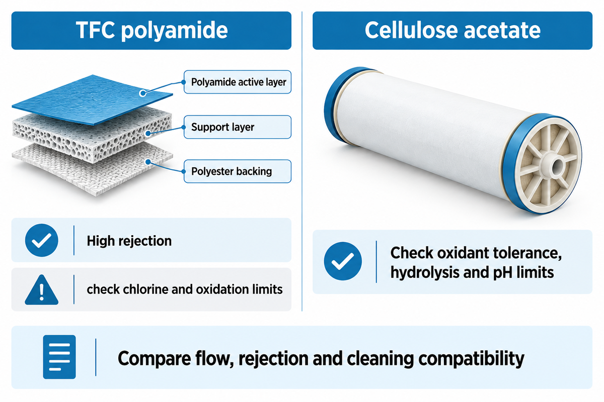
TFC polyamide elements are common in industrial applications because their thin selective layer allows salt rejection at practical flux. The U.S. Environmental Protection Agency workshop proceedings provide historical context for this material comparison. In a TFC spiral-wound element, the TFC polyamide layer sits above a support layer and a polyester backing. In situations where there’s tolerance to chlorine, legacy equipment, or a different cleaning regimen, a cellulose acetate element may be a better option.
| Feature | TFC polyamide | Cellulose acetate |
|---|---|---|
| Typical strength | High rejection and broad industrial availability | Greater tolerance of some oxidant exposure, subject to the product data sheet |
| Main caution | Residual chlorine and aggressive oxidation can damage the active layer | Hydrolysis, pH limits and lower rejection may matter in high-purity service |
| Buyer evidence | Salt rejection, permeate flow, chlorine limit, pH and cleaning compatibility | Same fields, plus hydrolysis and biological-control limits |
Material labels aren’t performance certificates. Behind every performance claim, consider the test water, pressure, temperature and recovery. A product sheet should state whether the value is nominal, minimum or a typical result.
Brackish, Seawater, Low-Pressure and Fouling-Resistant Elements
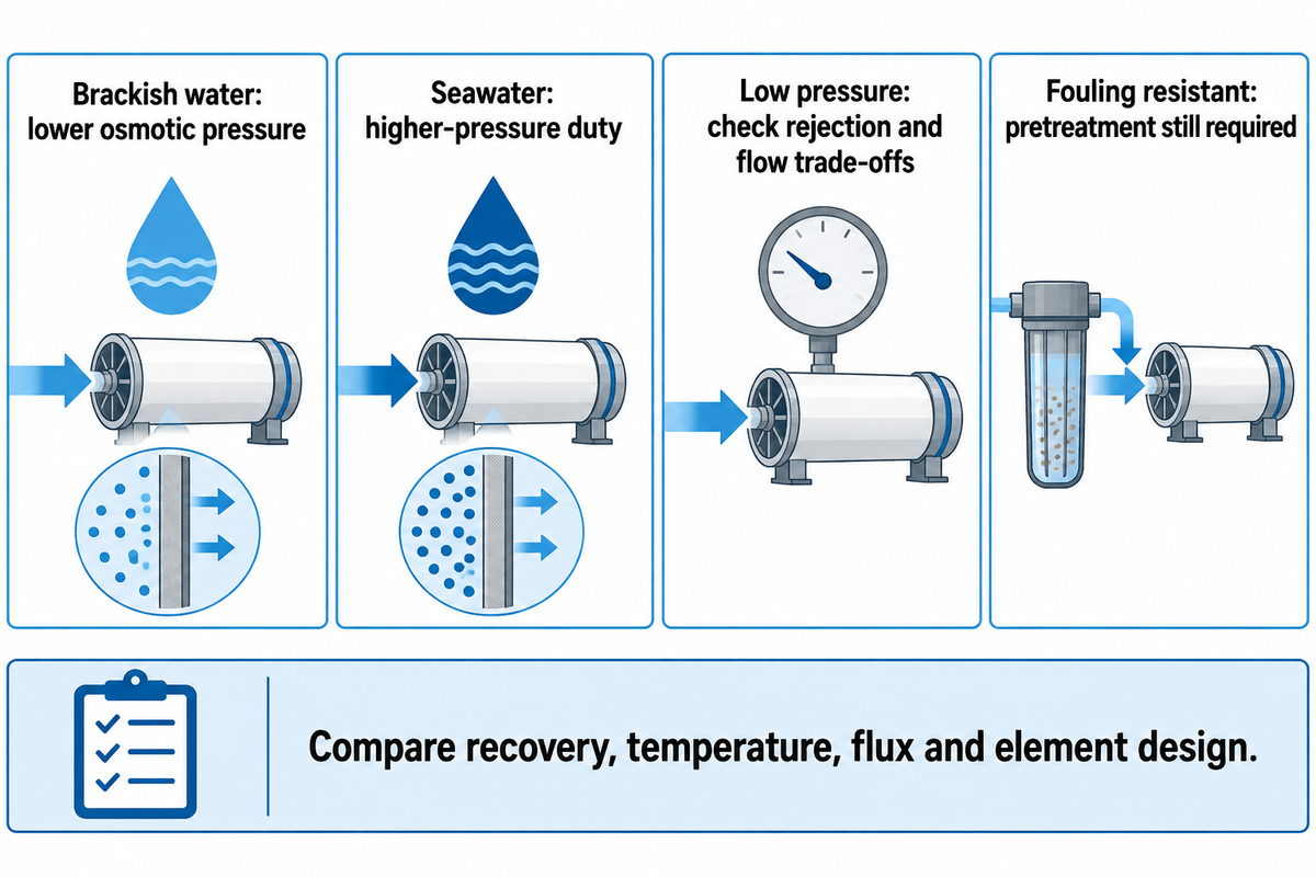
Brackish-water elements operate at lower pressure than seawater elements because feed osmotic pressures are lower. Kurita gives a typical brackish operating band of about 125–250 psi and describes seawater service around 800–1,200 psi for feedwater near 35,000 mg/L TDS. These are examples, not absolutes. Recovery, temperature, flux and element design still affect operation.
Ultra-low-pressure and low-pressure elements trade rejection and flow constraints for energy savings. Elements can be engineered to retain performance over time or made to be fouling-resistant by modifying the surface or spacer design. Fouling-resistant elements don’t reduce the burden for proper or adequate pretreatment.
For wastewater or reuse plants, the fouling inventory is a good starting point. Peer-reviewed literature reports that fouling increases pressure and decreases membrane life, while increasing chemical cleanings. Blue Membrane’s fouling-resistant reverse osmosis membrane element page is a good starting point for a product-specific perspective. Ultimately, your feed analysis and element cleaning strategy must be considered when choosing an element.
Spiral-Wound Construction and Nanofiltration Boundaries
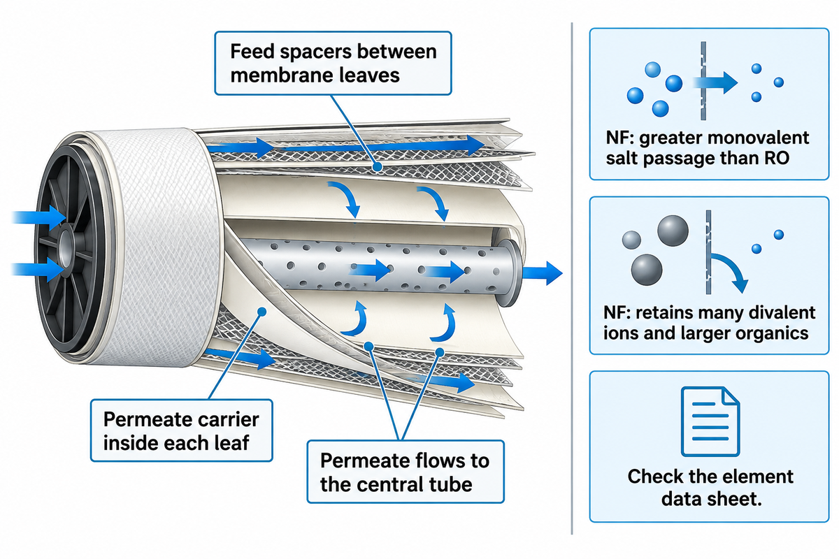
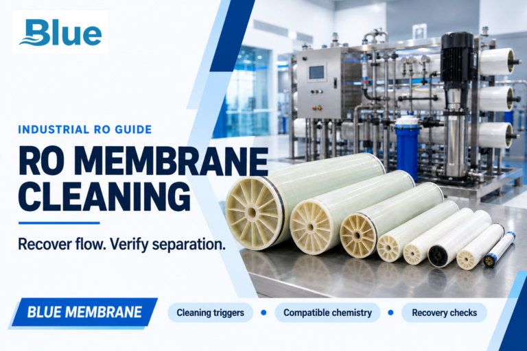
Most RO elements are spiral-wound, with feed spacers between membrane leaves and a permeate carrier inside each leaf directing permeate flow to the central tube. The DuPont FilmTec technical manual documents the element construction context. Spacer and feed channel geometry, along with element design, influence fouling.
Nanofiltration (NF) is distinct from RO. NF generally retains many divalent ions and larger organics and allows more passage of monovalent salts than RO. If the goal is to remove more hardness or selected organics rather than achieve near-total desalination, NF may require less energy and pressure than RO on the same feedwater. For better accuracy on rejection of different ions and organics, review the element data sheet.
Fouling, Scaling and Pretreatment: The Choice Changes Upstream
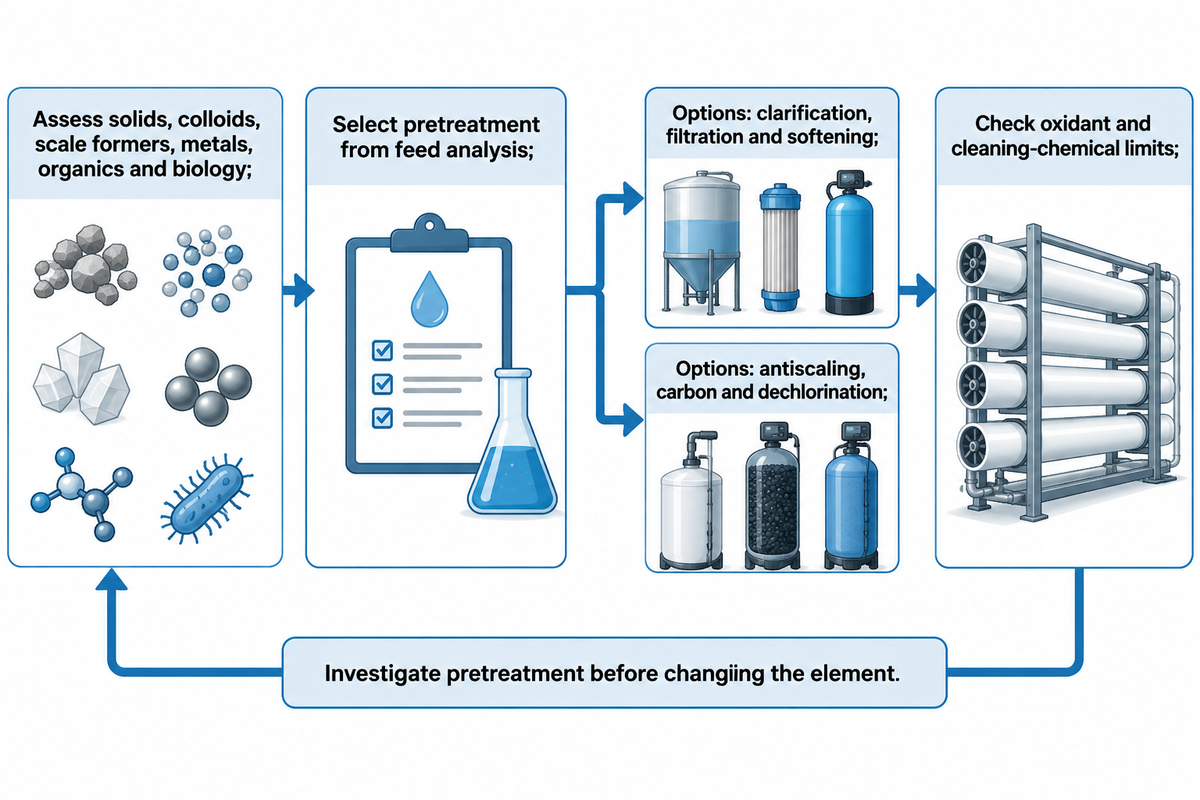
Fouling is a selection input, not merely a maintenance problem. The peer-reviewed fouling review in PubMed Central provides the supporting evidence. Suspended solids, colloids, silica, calcium carbonate, sulfate, iron, manganese, organics, microorganisms, and oil should be controlled prior to element selection. The pretreatment train may include clarification, filtration (either on beads or in cartridges), softening, antiscaling, activated carbon and/or dechlorination. The correct combination depends on the feed and the limits of the membranes.
Chlorine tolerance is a key selection trap. A polyamide element can lose rejection to an oxidant, even if it’s excellent initially. A second boundary is set by cleaning. A membrane may allow an alkaline clean, but have a different limit for an acid or a biocide. A polyamide name or number isn’t a reliable indicator of compatibility.
4040, 8040 and Replacement Compatibility
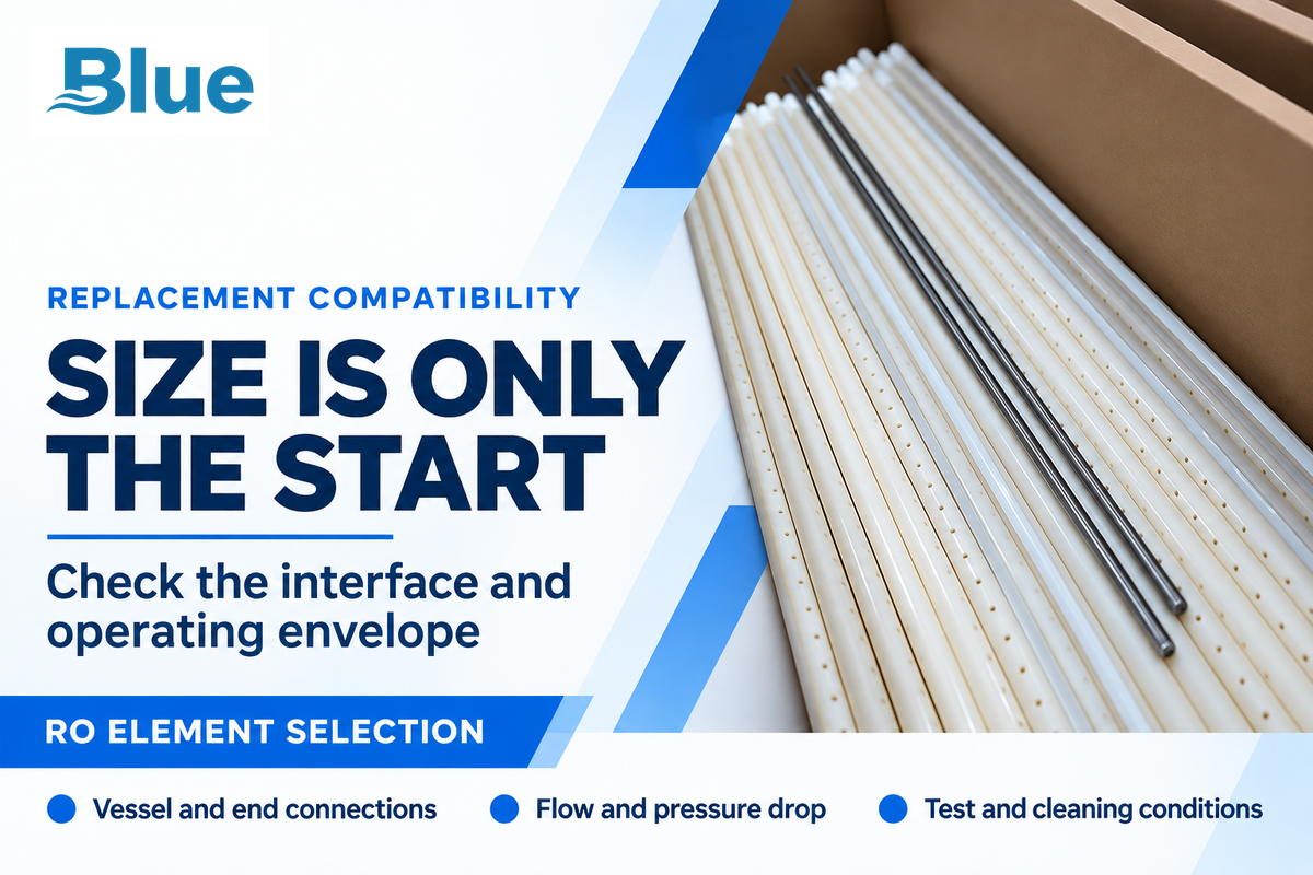
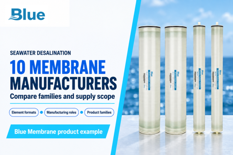
Elements in the nominal size classes of “4040” and “8040” aren’t automatically interchangeable. The DuPont FilmTec technical manual is the reference for element sizing and compatibility. That fit check follows the pretreatment limits above, because fouling and cleaning conditions also affect a replacement choice. A 4040 element is nominally four inches in diameter and forty inches long; an 8040 element is nominally eight inches in diameter and forty inches long. The vessel, end adapters, brine seal position, active length, permeate tube, maximum pressure drop and feed/concentrate flow must also be compatible.
Loyalmen’s BW-4040 comparison lists output of 2,400–2,600 GPD under its stated test conditions. Take that as a source-specific benchmark for 4040. Prior to a replacement order, check the old and new data sheets field-by-field.
- element dimensions and end connection;
- active membrane area and nominal flow;
- test water, pressure, temperature and recovery;
- maximum pressure drop and feed/concentrate flow;
- brine seal direction, vessel tolerances and cleaning limits.
This piece of evidence prevents the common error of assuming that the elements are the same just because they’re the same diameter.
The RO Membrane Specification Checklist
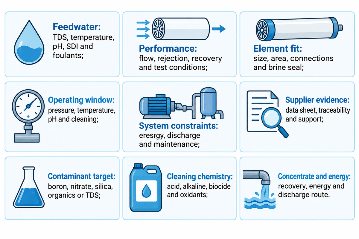
| Field | What to record | Why it matters |
|---|---|---|
| Feedwater | TDS, temperature, pH, SDI, hardness, silica, organics, oxidant | Sets osmotic pressure, fouling risk and chemical limits |
| Performance | Permeate flow, salt rejection, recovery and test conditions | Prevents apples-to-oranges comparisons |
| Element fit | 4040/8040 class, active area, end connections and brine seal | Protects vessel compatibility and loading |
| Operating window | Pressure, temperature, pH, pressure drop and cleaning limits | Defines the safe design envelope |
| System constraints | Energy price, concentrate route, discharge permit, maintenance access | Links the element to total operating cost and compliance |
| Supplier evidence | Current data sheet, lot traceability, technical support and replacement record | Turns a catalogue choice into a defensible purchase |
| Contaminant target | Boron, nitrate, silica, organics, pathogens or TDS | Prevents a generic salt-rejection claim from hiding a compliance gap |
| Cleaning chemistry | Acid, alkaline, biocide, oxidant and temperature limits | Protects the membrane surface during recovery cleaning |
| Concentrate and energy | Recovery, specific energy, concentrate route and discharge rule | Connects element choice to operating cost and permit risk |
Blue Membrane describes itself publicly as a professional RO membrane-element and integrated-system manufacturer serving more than 20 countries, with seven membrane series and custom capacities from 50 to 1,600 GPD. With the size and interface checked, the next step is to record the operating fields that make the replacement defensible. Their company statements can be found on their public About Us page. Confirm the exact series, test conditions and project fit for your application.
Provide your feedwater analysis and vessel data to Blue Membrane
Frequently Asked Questions
Are all RO membranes the same?
No. Although they both use reverse-osmosis separation principles, differences in materials, feedwater classes, surface treatments, element size, test conditions and spacers and element limits result in differences in active areas, pressure drops and flow limits. Treat them as alternatives only after a complete analysis of the data sheets and the vessel interface.
Which type of RO membrane is best?
The best type is the one that meets the contaminant and compliance target within the constraints of available pressure, energy, recovery, pretreatment, and cleaning. A seawater element isn’t always the best choice for a brackish stream, and a high rejection element may increase energy and fouling. Begin with feedwater analysis, establish a normalized performance goal and then select the material and duty.
How often should an RO membrane be replaced?
Various factors determine element replacement, including normalized permeate flow and salt rejection, differential pressure, and cleaning response. A calendar interval may mask chlorine damage, scale, or biological fouling. Trend normalized data, compare it with the supplier’s limits, and check pretreatment before deciding to change elements.
References and Sources
- Texas Water Development Board – Membrane Fundamentals for Water Treatment and Reuse
- Kurita America, Reverse Osmosis Membranes: System Design
- NIH/PMC, Fouling in reverse osmosis membranes
- DuPont FilmTec, Reverse Osmosis Membranes Technical Manual
- Google Patents, WO2025219561A1 regenerated-membrane system
- Blue Membrane, About Us
Quoted ranges are intended to give a general idea about a product. Regulatory and discharge decisions require recent project documentation and local review.
Engineering support
Need a membrane or RO system recommendation before your next quote?
Send feedwater data, capacity target, vessel size, operating pressure or replacement model details. Blue Membrane can help compare RO/NF grades, replacement options and system paths before you lock the specification.
RO / NF
Industrial membrane element selection
SWRO / BWRO
Desalination and brackish water systems
OEM match
Replacement and cross-reference support
RFQ checklist
What to include for faster model matching
- Water source and duty Well water, seawater, wastewater reuse, boiler feed, process water or potable water.
- Operating targets Feed TDS, flow rate, recovery, salt rejection target, temperature and pressure limits.
- Replacement context Current membrane model, element size, vessel count, fouling issue or cleaning history.
For urgent replacement checks, include photos of labels and vessel layout when available.