Get in touch with Blue Membrane Company

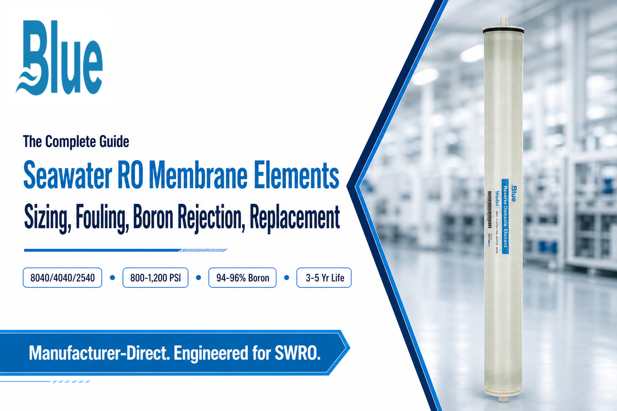
Quick Specs
| Feed TDS range | 32,000–45,000 mg/L (seawater classification) |
| Feed pressure | 800–1,200 psi (55–70 bar) |
| Salt rejection | 99.6–99.85% typical (TFC polyamide) |
| Single-pass recovery | 35–50% (osmotic-pressure limited) |
| Standard sizes | 2.5″×40″ / 4″×40″ / 8″×40″ |
| Typical service life | 3–5 years, up to 7 with strong pretreatment |
Seawater RO membrane elements are the workhorse of any seawater reverse osmosis (SWRO) desalination system – the replaceable spiral-wound cartridges actually performing the separation. The salt-, boron- and mineral-rejecting thin-film composite barrier in the membrane element allow water molecules to pass through while excluding dissolved solids present in seawater. This guide is written for system designers, engineers, buyers, and system integrators that want to understand the details within that cartridge, rather than only the complete system surrounding it.
Operating at 800-1,200 psi against feed concentrations between 32,000 and 45,000 mg/L TDS, a seawater reverse osmosis membrane provides an approximate rejection rate of 99.6-99.85% of the dissolved salts. Under typical operating conditions, it provides 3-5 years of service, and the life of the element is more a factor of fouling control and pretreatment discipline than simply time.
The following sections discuss construction details, sizing calculations, fouling modes, and indicators that will alert you to remove an element instead of cleaning it, and will be useful if you currently have Blue Membrane’s H1/H2 seawater elements, or are comparing specs among manufacturers. Getting element selection right is what separates a system that reliably delivers high-quality water at design flow from one that struggles with water quality shortfalls in its first year of using seawater as a feed source.
What Is a Seawater RO Membrane Element, and Why Does Feed Salinity Change the Design?
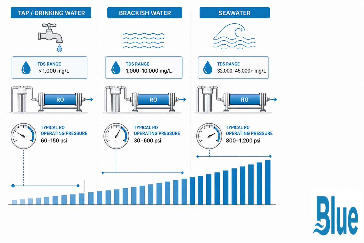
A seawater ro membrane element is a spirally wound cartridge, utilizing a thin-film composite (TFC) polyamide active layer that’s designed to function at the high pressure necessary to overcome seawater’s osmotic pressure. Seawater averages approximately 35,000 mg/L total dissolved solids according to the USGS. It’s the difference in TDS between seawater and other types of feed water that sets a seawater element apart from all other categories of RO membrane.
| Feed class | TDS range | Typical pressure |
|---|---|---|
| Tap / drinking water | <1,000 mg/L | 60–150 psi |
| Brackish water | 1,000–10,000 mg/L | 30–600 psi |
| Seawater | 32,000–45,000+ mg/L | 800–1,200 psi |
Higher concentrations of dissolved solids in the feed increase osmotic pressure-the minimum pressure the system must exert to cause water to flow across the membrane barrier-and this factor impacts many design considerations including element pressure rating, feed spacer design, and the required chemical resistance of elements. Using a brackish water rated element on seawater feed, rather than a specialized seawater element, will result in rapid failure, rather than simply lower performance. See our brackish water element guide for systems with < 10,000 mg/L TDS feed.
Inside a Seawater Element, Spiral-Wound Construction and What’s Different at 800+ PSI
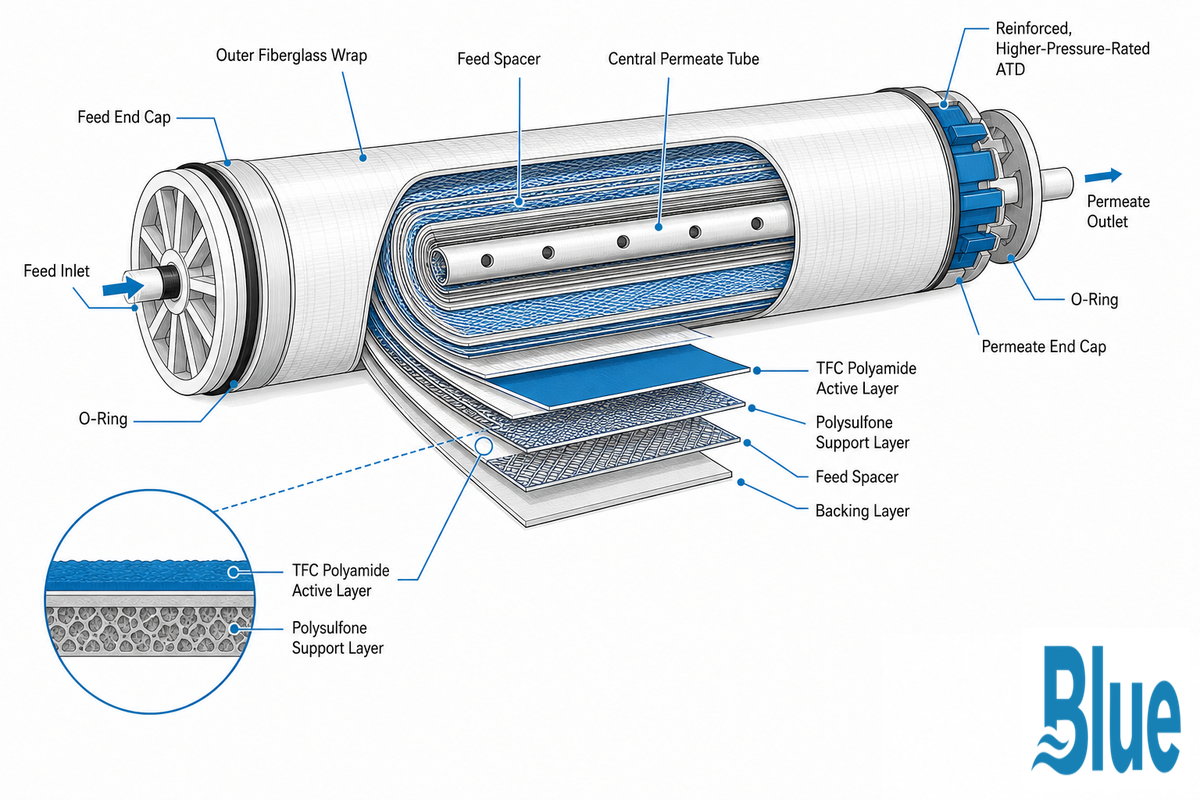
Every seawater ro membrane element element sold commercially today is based on the same architecture: a thin film of polyamide approximately 100-200 nanometers thick deposited over a microporous polysulfone substrate with a porous polyester cloth backing.
Individual leaves, or sheets, of the TFC material are layered and wound with a feed spacer to provide channels for feed water between leaves and a permeate tube at the center; this winding is placed in a cylindrical module sealed with end caps and end support discs and usually ATDs to prevent movement.
✔ Spiral-Wound (dominant format)
- Standard 8040/4040/2540 industry footprints
- Lower fouling sensitivity than hollow fiber
- Field-serviceable, standard housing compatibility
⚠ Hollow Fiber (niche format)
- Higher packing density, smaller footprint
- Narrow fiber lumens plug more easily
- Less common in new large-scale SWRO builds
The difference that defines the seawater class isn’t its chemistry family – it’s the elements what have to hold the 800-1,200 psi pressure continuously. ATDs, O-rings, and the outer fiberglass or ABS wrap on a seawater element are all made with a higher pressure rating than for their brackish-duty siblings, and the feed spacer design is tweaked to accommodate the increased fouling encountered from treating open-intake ocean water instead of filtered well water. When a brackish element is artificially pressurized to seawater-level operating pressure, the O-rings are far more likely to experience extrusion and the element may even “telescope” and fail long before the element’s membrane chemistry would reach its limits.
The Desalination Membrane Family Tree
There are three broad types of reverse osmosis membranes covering virtually every seawater installation: the standard thin-film composite (TFC) polyamide membrane, which is the standard offering at 99.6-99.8% rejection, but also TFC variations developed specifically to take single-pass boron rejection beyond 90%, and then there are the mostly-outdated cellulose acetate membranes, which tolerate continuous chlorine and operate below the rejection capabilities of polyamides. Knowing what kind of reverse osmosis element a datasheet is talking about – not just the headline rejection number – is the first filter one should make when comparing elements across membrane types. Innovation continues in membranes for desalination, such as a method that takes the rejection for a particular TFC element and improves upon it, disclosed in US Patent 7,491,334 B2 for a polyamide RO membrane post-treatment.
Element Sizing, Matching 8040 / 4040 / 2540 to Your Capacity Band
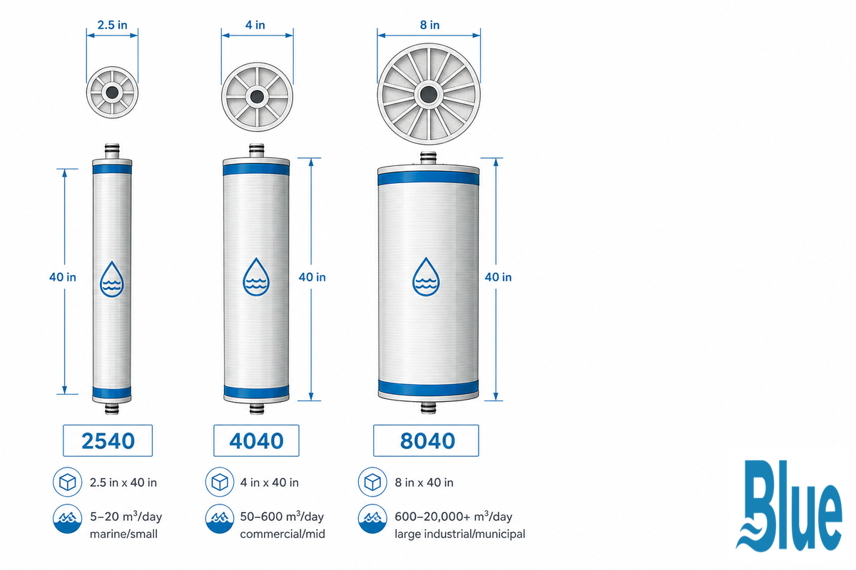
Element dimensions are referenced by the standard 8-in.-diameter by 40-in.-length 8040 elements; 4-in.-diameter by 40-in.-long are 4040s; and 2.5-in.-diameter by 40-in.-long are 2540s — a nominal-diameter convention that spans manufacturers rather than being brand-specific, as desalination engineering patent literature confirms (US20070272628A1), and one that holds whether the SWRO elements in question are DuPont FilmTec seawater lines, Applied Membranes product lines, or AMI membrane elements, all reporting water production capacity on the same like-for-like sizing basis. The appropriate size is selected based on capacity needed, not personal preference; because seawater systems can operate only up to a fraction of the recovery rates achieved in brackish systems, this sizing must take that constraint into account from the beginning. Manufacturers often list element production as GPD (gallons per day) instead of m³/day; one may estimate 1 m³/day is equal to 264 GPD.
| Capacity band | Typical output | Element size | Typical deployment |
|---|---|---|---|
| Marine / small | 5–20 m³/day | 2540 | Watermakers, yachts, small land-and-sea units |
| Commercial / mid | 50–600 m³/day | 4040 | Resort/island skids, containerized units |
| Large industrial / municipal | 600–20,000+ m³/day | 8040 | Multi-vessel arrays, coastal plants, refinery process water |
Elements are loaded into 8040 pressure vessels in a series arrangement of 6-7 elements per vessel. Concentrate from each element is passed through the next, progressively increasing the salt concentration, while permeate from each element is removed along the entire series. Upstream elements process the least concentrated feed and typically operate at higher flux levels, while down stream elements, treating increasingly concentrated reject, are operated at lower flux levels to prevent design failure from increased fouling potential.
Capacity-Band Sizing Decision
- Under ~20 m³/day → 2540, single or dual-element housing
- 20–600 m³/day → 4040, multi-element FRP or stainless housing
- 600+ m³/day per vessel → 8040, stainless steel multi-element pressure vessel, 6-7 elements per vessel
Housing Compatibility Is Not Pressure-Rating Compatibility
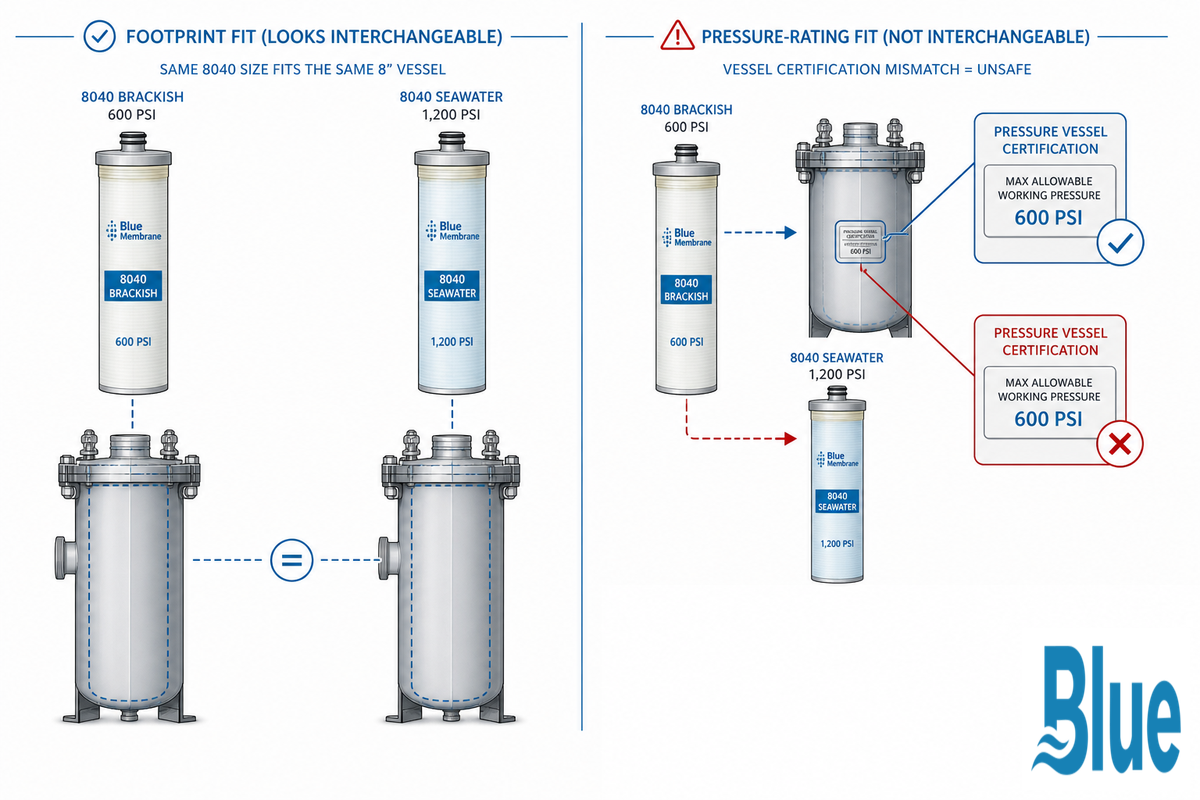
Since 8-in.- and 4-in.-element sizes are a standard, not a manufacturer-specific design, a 40-in. element from Brand A can usually fit into an 8040 housing that’s manufactured by Brand B, assuming the elements have the same “series designation.” That fact is routinely overemphasized, leading to a potential risk specific to seawater applications.
⚠️ Important
Footprint Fit Vs. Pressure Rating Fit Both 8040’s fit the same housing material and if they were brackish duty element rated 600 psig vs a seawater rated 1,200 psig, it could lead to a mechanical failure to mix them in the housing not necessarily just a loss in efficiency.
The housing or pressure vessel is included in that as well. A housing originally designated and certified for brackish-duty operating pressure can’t simply be given a higher-pressure element inside – the housing’s own pressure-vessel design and certification (often done per ASME-style pressure vessel codes for desalination service, see US20110290728A1, SWRO Pressure Vessel and Process for the pressure-class design considerations involved) must match the seawater operating class before any element swap is safe.
“A senior water treatment engineer on Eng-Tips put it plainly when discussing membrane selection for a mixed-salinity application: use a sea water membrane because it carries higher operating pressure and better salt rejection even at lower pressures and salinities than a purpose-built brackish element would deliver.”
What Actually Fouls a Seawater Element, Marine Biofouling, Colloidal Solids, and Scaling
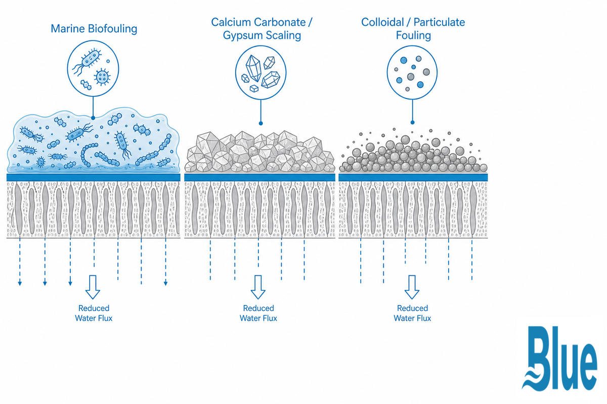
The key factor governing frequency of cleaning and eventually replacement of the seawater element is Fouling – not age. Since the seawater elements extract water from the open ocean and not the brackish water from a filtered groundwater source, the fouling character differ from that seen in a brackish well water system in a substantial way.
| Fouling type | Indicator | Countermeasure |
|---|---|---|
| Marine biofouling (biofilm/EPS) | Rising differential pressure (pressure drop), often before flux declines | Dechlorination + non-oxidizing biocide dosing, CIP with biocidal cleaner |
| Algal bloom / HAB colloidal loading | SDI spikes during bloom events, seasonal turbidity swings | Coagulation/flocculation ahead of UF, intake monitoring during bloom season |
| General colloidal / particulate | SDI₁₅ > 3 | Coagulation/flocculation + ultrafiltration (UF) filtration pretreatment ahead of the element |
| Calcium carbonate (calcite) scaling | Flux decline concentrated at tail elements, high-recovery operation | Acid dosing to control carbonate scaling, antiscalant sized to recovery target |
| Calcium sulfate (gypsum) scaling | Flux decline without dP rise, worse at high recovery + low antiscalant dose | Antiscalant matched to feed sulfate/calcium chemistry, recovery-rate limiting |
| Barium/strontium sulfate scaling | Localized tail-element scaling despite normal antiscalant dosing | Sulfate-specific antiscalant, recovery limiting where Ba/Sr present in feed |
| Silica scaling | Reactive silica approaching saturation at operating recovery (less common in SWRO than brackish) | Recovery-rate limiting, silica-specific antiscalant where feed silica is elevated |
| Chemical / oxidative attack | Residual free chlorine present without dechlorination | Sodium metabisulfite (SMBS) dechlorination ahead of the polyamide element |
| Membrane compaction (non-fouling) | Gradual flux decline over years under sustained high pressure, no dP signature | Not cleaning-fixable — a replacement signal, not a pretreatment gap |
The most independent single cause for the difficulty of controlling is Marine Biofouling – as one well-regarded peer-reviewed RO fouling review and several industry technical documents note biofilm on open-intake seawater feed as the controlling operating factor for non-brackish feed conditions, whereas for a well-fed brackish application scale may control over biofouling. But, it’s not all about brackish; one PubMed referenced study noted the occurrence of gypsum and calcite scaling in commercial SWRO membranes that created flux losses when recovery rates were high, or the antiscalant dosing hadn’t been optimized to reflect feed chemistry. The reality is biofouling-controlled with some other issues.
💡 Pro Tip
Chlorine must never be continuously dosed ahead of a polyamide seawater element – this attacks the active layer. If chlorine is utilized for the intake biofouling control, it is essential to completely remove all residual chlorine using sodium metabisulfite prior to the water reaching the membrane.
Operating Parameters, Pressure, the 50% Recovery Ceiling, and the Boron Rejection Problem
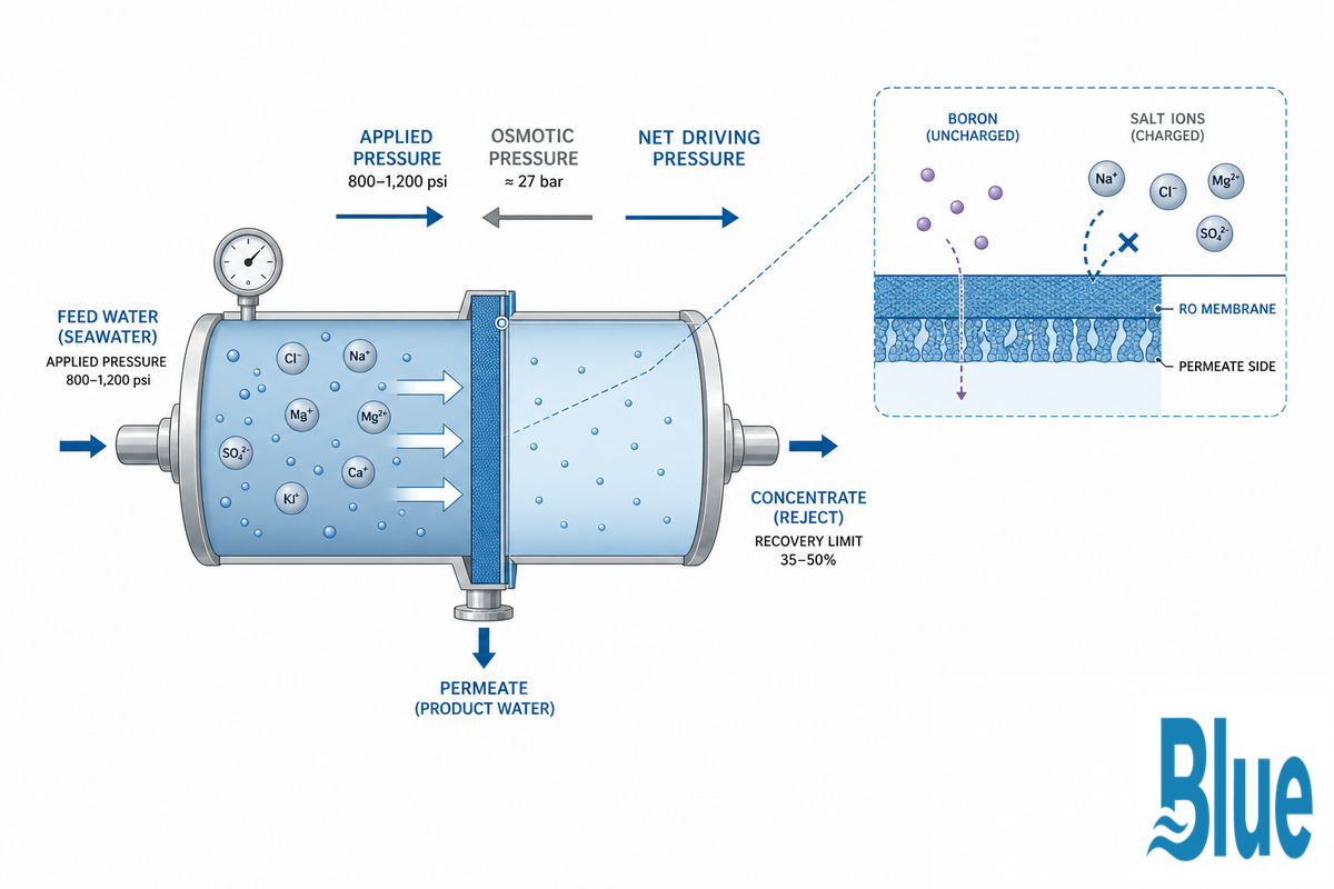
When pressure above the normal osmotic pressure of the feed water is imposed across the membrane, water is made to travel against its natural diffusion path in opposition to the direction of natural diffusion – a process driven by high-pressure feed pumps (typically drawing 5 kW to 7 kW per pressure-vessel array) whose energy consumption is the single largest line item in a SWRO plant’s power budget, and one that low-energy pump technology can reduce but not eliminate, since feed water temperature (commonly 15°C to 30°C depending on region and season) and salinity both still set the physical energy floor. In typical seawater condition (TDS approximately 35,000 mg/L, dominated by dissolved sodium chloride), osmotic pressure is around 27 bar. Hence, in SWRO, the feed pressure is applied at a range of 55-70 bar, to obtain the net driving pressure above osmotic pressure to allow producing flux.
📐 Engineering Note — Worked Example
Osmotic pressure goes approximately with feed TDS. A unit designed for 33,000 mg/L Atlantic seawater needs to overcome some 27 bar osmotic pressure; a similar unit designed for 45,000 mg/L Arabian Gulf needs to overcome approximately 45,000 / 33,000 * 27 bar = 37 bar – some 10 bar more, not including any fouling margin. That’s why a unit designed for one coast isn’t necessarily suitable for another without re-confirming feed TDS and resizing pump and pressure class.
Single-pass seawater recovery (proportion of feed water that ends up as permeate) usually tops out at between 35-50%. It’s limited by the concentrate’s osmotic pressure, which rises progressively along the length of a pressure vessel as the water get concentrated further; exceeding the designed recovery will force elements at the far end of a pressure vessel to operate against concentrate that approaches their own maximum pressure limit and the fouling risk will rise well before reaching that limit. This is a real physical limitation and not some conservative marketing number – the concentrate osmotic pressure is the same for all manufacturer’s elements.
Why Isn’t Higher Rejection Automatically Better?
Assuming the highest-rejection element is the best choice seems reasonable, but independent analyses don’t support it as a rule. One analysis of two-pass seawater desalination found maximum membrane rejection didn’t “necessarily yield higher overall system efficiency,” and a separate analysis of high-recovery SWRO confirmed maximizing recovery alone is “rarely cost-effective.” The best choice depends on feed salinity, temperature, and end use, not on maximizing a single number.
The Boron Rejection Problem
Boron rejection. Standard salt-rejection numbers don’t address boron. This is because boric acid is a small and mostly uncharged species at the pH of seawater, so it’s not as effectively rejected as ions like sodium or chloride.
~90%
Typical single-pass boron rejection, standard TFC chemistry
94–96%
Boron-selective TFN chemistry, per element
Commercial SWRO membranes are commonly reported to achieve around 90% or slightly higher single-pass boron rejection under standard test conditions — the boron-rejection mechanisms behind that figure (pH- and ionic-strength-dependent behavior of boric acid versus borate) are examined in a 2024 peer-reviewed study on predicting SWRO boron rejection. High-rejection, boron-selective TFN elements from specialty manufacturers are available that can offer boron rejection of 94-96% per element, based on proprietary chemistries; this figure will vary by manufacturer and specific chemistry, and it isn’t a universal constant across every membrane on the market. The best way to reduce boron rejection to very low levels is through a second pass using adjusted pH to convert more boron into its charged form, borate, which is more readily rejected.
⚠️ Regulatory Note, Boron Limits Aren’t One Number
While WHO publishes a boron target of 2.4 mg/L for drinking water, WHO itself points out that local regulators will accept higher values when the target is hard to meet consistently due to high-boron source water or due to a supply being entirely from a desalinated source. In the US, EPA publishes boron levels as an informal health advisory, and not an enforceable federal standard for drinking water. What level you need to meet will depend on your specific regulator or your customer – not the single world standard. Be sure you know what that standard is before you make the assumption that single-pass is enough.
Data from manufacturers show exactly why you should never think of boron and salt rejection as the same number: in its analysis of over 500 autopsy data, Blue Membrane found fouling driven degradation in both flux and rejection in every single manufacturer’s elements it’s examined – so that number in the datasheet from time of installation is just the start.
When to Replace a Seawater Element, Signals and Typical Service Life
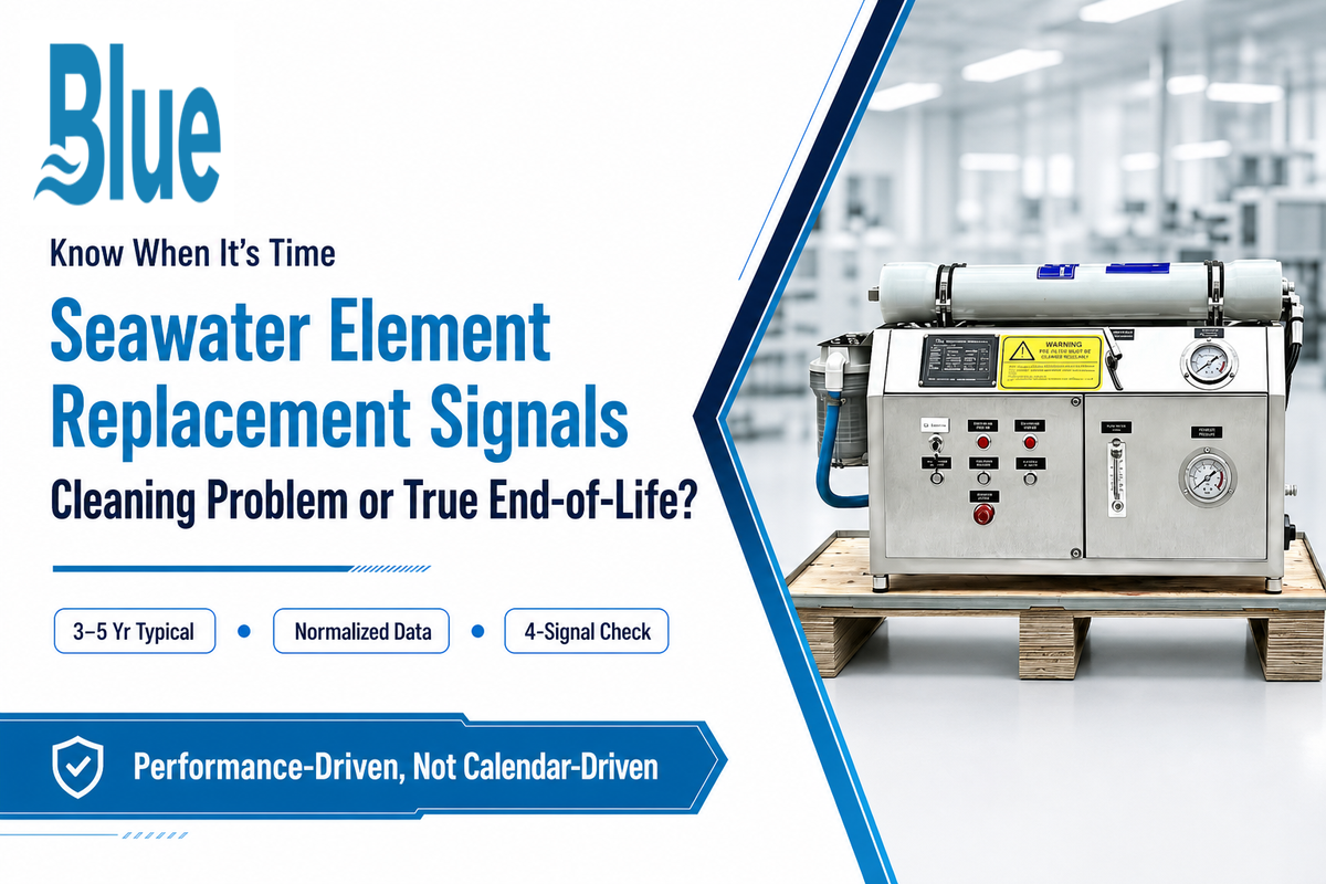
Most performance loss in seawater element applications is a cleaning problem, not a reverse osmosis membrane replacement problem – what many buyers search as “RO membrane replacement.” Bureau of Reclamation research found cleaning frequency alone can represent 2-15% of total plant operating cost (USBR Report 106), which is exactly why the cost of seawater RO operation hinges on telling a cleaning-fixable decline apart from a true end-of-life element.
The Rejection-Decline Replacement Curve — 4 Signals
- Normalized permeate flow 10-15% or more below its initial baseline after a full cleaning cycle
- Normalized salt passage 10-15% higher than its initial baseline (reject trending below its normal 99.6-99.85% range)
- Normalized boron passage higher than its baseline even while salt rejection remains steady – a critical indicator specific to potable/agricultural use that will be missed by pure salt-rejection measurement
- Normalized differential pressure across the vessel stage or the individual element is 15% or more higher than its baseline and doesn’t respond to cleaning.
One signal trending down is normally enough to suggest cleaning; two or more trends following a properly executed CIP are much stronger indications that the element has simply reached its end-of-service life. Repeatedly cleaning a truly dead element wastes chemistry and downtime without any possibility of restoration, exactly the failure that the autopsy data are designed to catch. Elements that hold stable salt rejection and consistent membrane performance through repeated cleaning cycles protect system performance and total lifecycle cost – the ones that don’t are the actual replacement candidates, cleaning problem or not.
💡 Planning Benchmark
seawater element have been observed in service for 3-5 years typically, and some have been reported to run as long as 7 years, particularly in applications with strong pretreatment and diligent cleaning practices – but the longer end of this range come from manufacturer reporting and general industry practice, not definitive long-term studies. Some isolated sources cite up to 10 years for particularly well-maintained systems, but this shouldn’t be considered a typical planning value.
Where Seawater Elements Are Deployed
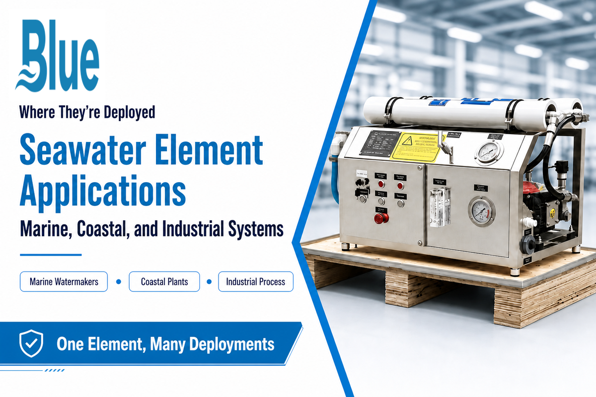
Seawater element applications start wherever the brackish threshold is exceeded. A marine RO system built for shipboard applications prioritizes compact footprint and high productivity per square foot of skid space, while a land-based coastal plant scales toward municipal volume instead – this land-and-sea based range is why a marine watermaker vessel designed for marine applications, a sea-based desalinator, and a coastal plant will differ dramatically in skids, power requirements, and control philosophy.
- Marine watermakers – vessel, yacht, cruise ships, offshore platform
- Land-based coastal desalination – islands, resort towns, small communities
- Industrial process water – refinery operations, coastal manufacturing plants
- Municipal desalination at scale – multi-vessel arrays, large coastal plants
For marine and vessel-based installation projects, our marine water makers guide covers the installation-related engineering. For containerized or skid-mounted land-based installations, see the containerized & skid-mounted SWRO systems guide – both go deeper on system-level design than the element-focused scope of this article.
Industry Outlook, What’s Changing in Seawater Membrane Technology
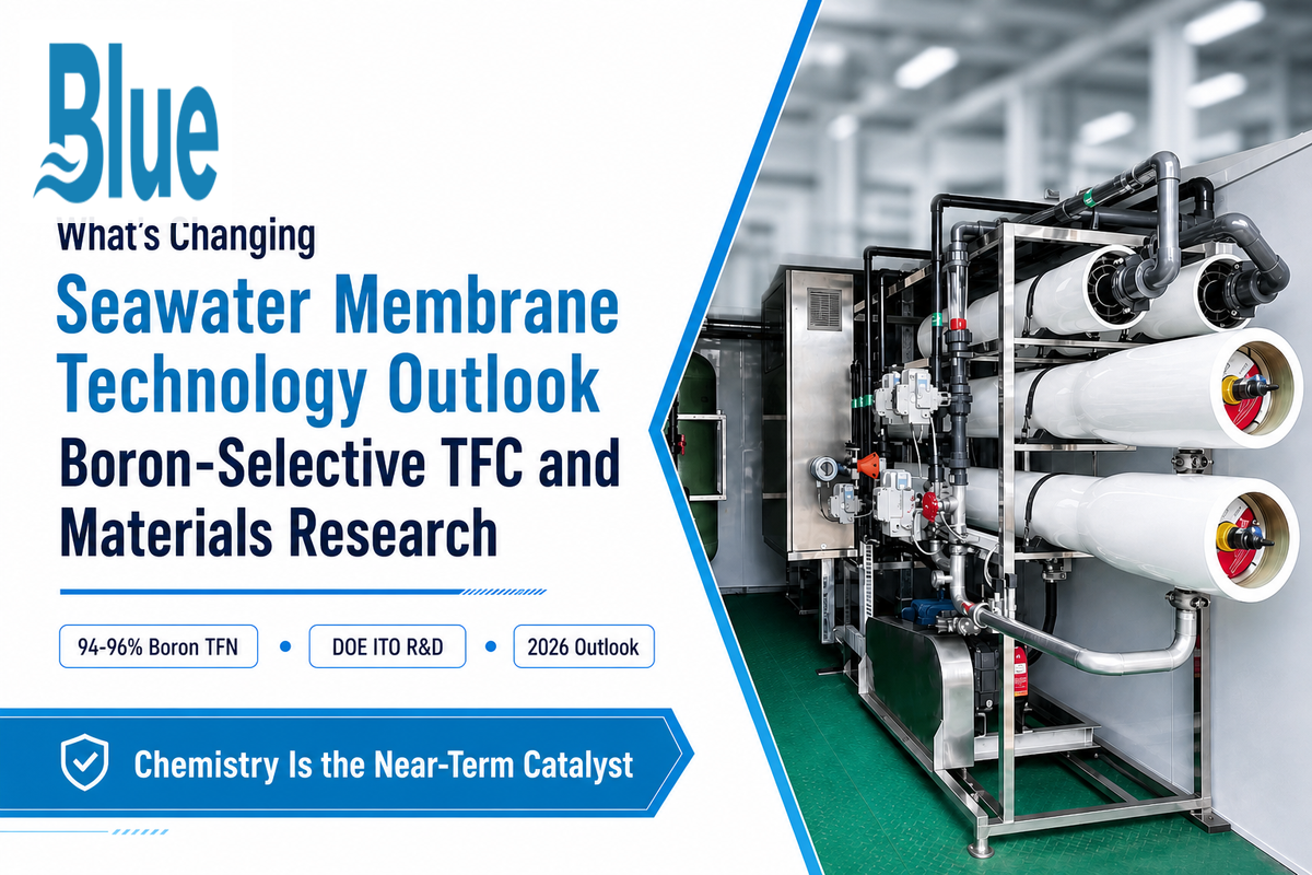
The closest thing to a near term catalyst here isn’t a demand play – there’s been no increase in the search interest in seawater membrane terminology in the past year – but rather chemistry. TFC alternatives specific to boron, which are now in use today and have been reported independently in numerous case studies at 94-96% single pass boron removal per element, are moving previously second-pass removal to the first-pass category for an increasing share of applications. For purchasers who must achieve a strict level of boron for potable or irrigation uses, this represents an opportunity to re-evaluate if the need for two-pass systems should still drive their decisions before a system design is locked down for years ahead, starting in 2026.
Materials Research Is Still Moving the Baseline
Beneath this the material’s science work has been driving the underlying membrane chemistry: in a 2025 peer-reviewed review of nano-structured RO membrane materials authors mentioned work continuing to improve permeability and salt rejection, “in an effort to minimize fouling propensity and power consumption for a unit of product water”; slow and steady progress rather than a jump. This mirrors the Department of Energy’s own posture on the technology, whose Industrial Technologies Office is directly funding research, development, and demonstration work aimed at more cost-effective, efficient desalination membranes (DOE Industrial Technologies Office). Exactly where the last decade of commercial membrane products have been progressing actually.
💡 Market Context Only
Estimates of market size for membrane technology (multiple research firms report market size in the tens of billions of dollars, with high single-digit to low double-digit CAGR rates out to 2033) are only directional context – don’t use these as justification alone for changing a spec choice. The same directional caution applies to any RO desalination or RO seawater market forecast cited elsewhere – treat the percentage, not the underlying spec recommendation, as the moving target.
This broader push toward more efficient seawater reverse osmosis systems is part of a wider water desalination push across desalination applications beyond just membrane chemistry – energy recovery devices, intake design, and pretreatment are all advancing in parallel, but membrane element chemistry remains the single biggest lever for total system cost.
FAQ
Q: What’s the difference between a seawater element and a brackish element?
View Answer
The basic TFC polyamide chemistry is identical, but a seawater element is engineered to handle continuous operation in the 800-1200psi pressure range versus the brackish-rated range of 30-600psi and includes higher pressure ATDs, O-rings and outer wrap. Trying to operate a brackish-rated element at high pressures would most likely cause a mechanical failure long before the chemistry even became an issue and a brackish-rated element could not achieve the required recovery or rejection of a true seawater duty cycle.
Q: Can a seawater element run on brackish feed?
View Answer
Physically yes – a seawater element doesn’t break in low salinity feed water, since it’s simply built for a higher pressure and salt-load ceiling than the feed is asking of it. Economically no – you’re buying pressure rated construction and boron optimized chemistry that you do not require at brackish TDS when a specifically designed brackish element will give you equivalent or higher flux at substantially lower pressure and power consumption. The mismatch shows up most clearly on the utility bill, not in any failure mode, which is why it’s easy to overlook during initial system specification.
Q: What does “99.8% rejection” actually mean on a datasheet?
View Answer
This is a test-condition specific number not an absolute, usually reported at a particular pressure (often somewhere in the vicinity of 800psi) with a certain % recovery and at 25C on a particular standard feed. Rejection at your actual working conditions, your particular feed chemistry and pressure will be different – potentially substantially. Even two different membrane elements both reporting 99.8% could be from different test conditions from different manufacturers.
Ensure you know the basis of reported values when comparing headlines from different brands and get them validated on your feed water after installation.
Q: How is boron rejection different from salt rejection?
View Answer
Salt ions such as sodium and chloride are negatively charged and are thus easily rejected by polyamide membranes, often greater than 99.6%. Boron, typically in the form of neutral boric acid at ambient pH in seawater, is rejected less readily-a standard element may approach 90% single pass boron rejection and a boron selective element can get into the mid-90s. Having a high salt-rejection specification will not necessarily guarantee a similar high boron-rejection spec for that same element.
Q: What’s the typical lifespan of a seawater element?
View Answer
Typically 3-5 years, sometimes 7+ with strong pretreatment and cleaning discipline. This is a planning range, not a guarantee – fouling management drives actual lifespan, not the calendar.
Q: Do all 8040 elements fit the same housing?
View Answer
Physically, for the most part yes. The 8” diameter, 40” length housing configuration is a generic industry standard, not a specific Blue Membrane design, so physical cross compatibility is widespread. However, you need to ensure the housing pressure rating and the element pressure rating (and in some cases the chemistry and effective area) are suitable for the system’s intended operation. A physically “compatible” housing is not a substitute if the pressure rating doesn’t align. Check the datasheets for more than just the physical dimensions! This physical-fit-versus-pressure-fit distinction is exactly where field mistakes happen most often: a housing originally certified and installed for brackish-duty operating pressure cannot simply receive a higher-pressure seawater element without the vessel itself being re-certified to the seawater pressure class, since housing certification follows ASME-style pressure vessel codes rather than the element’s own datasheet. Treat the housing and the element as two separate purchasing decisions with two separate pressure ratings to confirm, not one.
Why We Write This
Blue Membrane produces seawater, brackish water, and nanofiltration RO elements that are distributed through our network of OEM, system integrator and distributor partners. This guide was developed to address what we see as common errors made in purchasing decisions at the element level – housing mismatches by pressure rating, incorrect data pulled from the wrong line of a datasheet, and premature cleaning procedures on an aged element – errors which ultimately result in field failures for our customers.
References & Sources
- Saline Water and SalinityU.S. Geological Survey
- Fouling in Reverse Osmosis Membranes: Monitoring, Characterization and MitigationPMC / peer-reviewed
- Mineral scaling on commercial seawater RO membranesPubMed / peer-reviewed
- Predicting the Boron Removal of Reverse Osmosis MembranesScienceDirect / peer-reviewed (Chong et al., 2024)
- Evaluation of Membrane Pretreatment for Seawater DesalinationU.S. Bureau of Reclamation
- ISO 25175: RO/NF Membrane Element Performance Test MethodInternational Organization for Standardization
- Health Advisory Summary for BoronU.S. Environmental Protection Agency
- Boron in Drinking-Water, Chemical Fact SheetWorld Health Organization
- US Patent 7,491,334 B2, Method of Treating RO Membranes for Boron Rejection EnhancementUSPTO
- US20070272628A1, Apparatus for Treating Solutions of High Osmotic StrengthUSPTO
- US20110290728A1, SWRO Pressure Vessel and ProcessUSPTO
- Desalination BasicsU.S. Department of Energy, Industrial Technologies Office
Related Articles
- Seawater RO Membrane Elements (H1/H2 Series)cross-reference specs, TCO model, and RFQ for Blue Membrane’s own elements
- Seawater RO Systems Guidewhole-system RFQ decisions: pretreatment, energy recovery, deployment matching, cost
- Brackish Water RO Membrane Elements: Complete Guidethe lower-salinity counterpart to this guide
- Marine Water Makers Guidedeployment-specific engineering for vessel and yacht systems
- Containerized & Skid-Mounted SWRO Systems Guideland-based packaged system engineering
- Standard Nanofiltration Membranesfor selective softening rather than full desalination