Get in touch with Blue Membrane Company

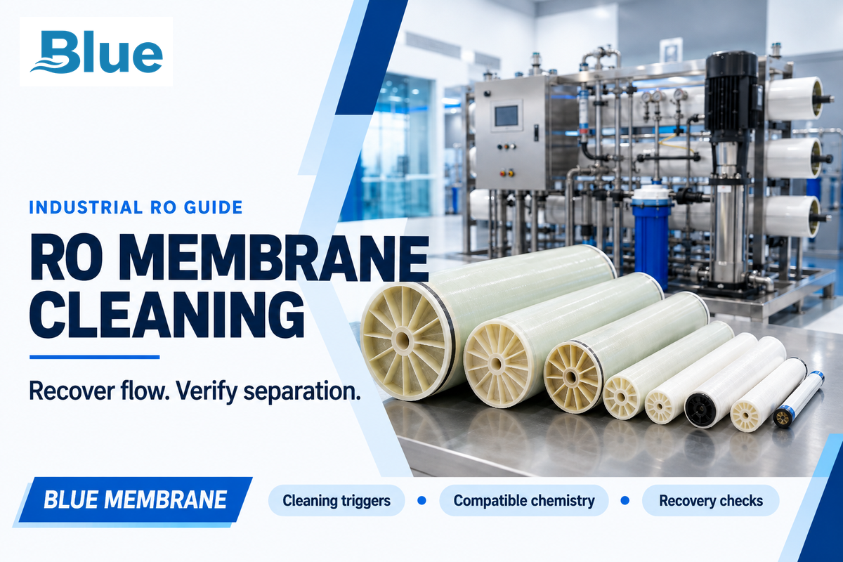
RO membrane cleaning removes deposits using membrane-compatible chemicals with controlled circulation. A 10% drop in normalized permeate flow is one cleaning trigger for FilmTec elements. Choose the cleaner for the deposit and remain within the limits of the installed model. Then, check the flow, salt passage and pressure drop in combination.
A recovered flow meter reading may mask poor rejection. Restored system performance requires both output and separation. This guide explains industrial clean-in-place, or CIP, from diagnosis to restart, including when acid-first advice fails and what an off-site cleaning quote leaves you to budget.
By Cherry · Updated October 2026
Quick Specs
| Application | Industrial spiral-wound reverse osmosis elements |
|---|---|
| Cleaning trigger example | FilmTec: normalized flow down 10%; other signals below |
| Chemistry | Deposit-specific acid, alkaline or formulated cleaner |
| Operating limits | Model-specific pH, temperature and exposure time together |
| Acceptance | Performance comparison plus the required product-water tests |
- Normalize operating data before diagnosing fouling.
- Separate carbonate scale from sulfate scale, silica and biological deposits.
- Rinse between incompatible cleaning stages and protect the product-water circuit.
- Track how long recovery lasts after the system returns to service.
RO Membrane Cleaning: What Can Be Cleaned?
Industrial reverse osmosis membrane cleaning is performed to remove deposits on the membrane surface and feed spacer. To clean a reverse osmosis element, reversible fouling is removed by compatible chemistry and circulated away. Cleaning doesn’t repair an oxidized separation layer, torn sheet or leaking interconnector. Faults require diagnosis and repair or replacement.
Can an RO filter membrane be cleaned?
Many industrial RO elements can be chemically cleaned in their pressure vessels, or by a specialist off-site service. A domestic RO water filter may instead use replaceable cartridges and a separate housing-sanitation procedure. Equipment instructions determine which parts remain installed. A household RO water purifier procedure isn’t an industrial cleaning recipe.
To clean and sanitize a reverse osmosis system, distinguish the jobs first: flushing moves water through the equipment, chemical cleaning removes deposits, and sanitizing addresses microorganisms under a separate approved procedure. Instructions to sanitize a reverse osmosis housing may require removing the membrane and carbon cartridges. Never assume the same chemicals can contact all the components of a water filter system.
The spiral-wound membrane structure explains why a hollow-fiber backwash routine cannot simply be transferred to conventional RO elements. Make sure you check the approved flow direction and pressure limits before you clean your RO elements.
Cleaning Triggers: Flow, Salt Passage and Pressure Drop
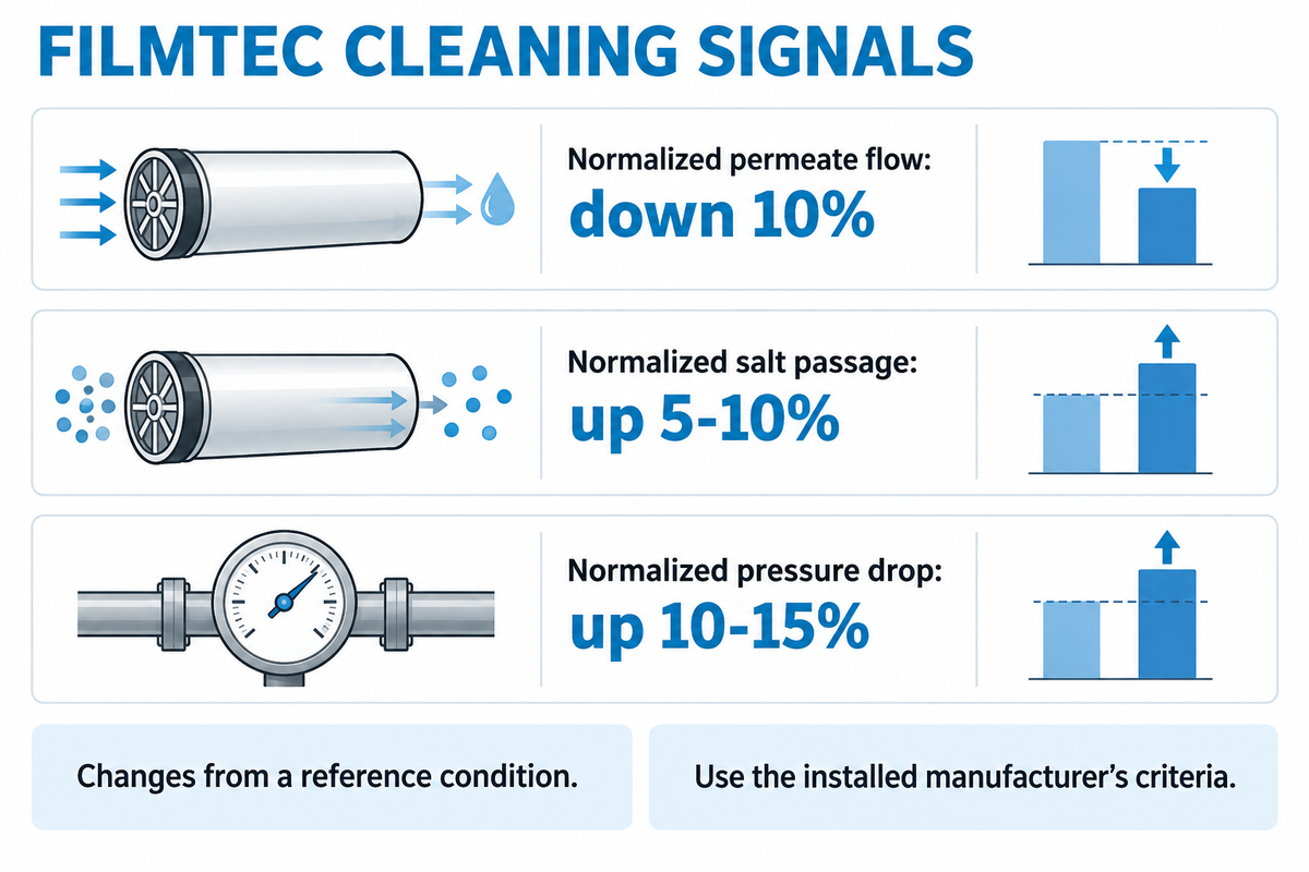
FilmTec guidance identifies three cleaning signals: normalized permeate flow falling 10%, normalized salt passage rising 5–10%, or normalized pressure drop rising 10–15%. These are changes from a reference condition, not three absolute instrument readings. Any signal deserves investigation; the installed element manufacturer’s criteria govern the cleaning decision.
When Should RO Membranes Be Cleaned?
Following best practices, cleaning is performed when confirmed performance deterioration meets the cleaning criteria of the membrane element and fouling is the cause. The best practices for cleaning RO membranes start with diagnosis: exclude cold feedwater, altered recovery, pressure-control problems and bad instruments. Normalization is used to compare performance of the elements at similar conditions and fouling is distinguished from changes in the processed water or system.
| Normalized signal | Change from reference | Check before choosing chemistry |
|---|---|---|
| Permeate flow | 10% decrease | Temperature, feed pressure, recovery and flow-meter accuracy |
| Salt passage | 5–10% increase | Conductivity measurement, feed conditions and possible leaks |
| Pressure drop | 10–15% increase | Comparable flow conditions and which stage is affected |
These are excerpts from DuPont’s FilmTec cleaning guidance. ASTM D4516-19a provides information on standardizing RO performance data and is not a cleaning-specification document. As stated, its scope covers waters including brackish water and seawater and may not apply to wastewater. When evaluating the stages, use a normalization method appropriate for the feed water and assess each stage separately.
Illustrative operating example: a plant’s normalized flow falls from 100 to 88 m³/h. The decline is (100 − 88) ÷ 100 × 100 = 12%. Over the same period, normalized salt passage increases from 0.30% to 0.33%: (0.33 − 0.30) ÷ 0.30 × 100 = 10%. The latter is only 0.03 percentage points, but it’s a 10% relative increase. Both merit investigation against the applicable criteria. If the apparent flow loss disappears after correcting for colder feedwater, adding cleaner won’t solve that temperature effect. Keep the baseline and normalization method with the trend so the next shift can reproduce the comparison.
Cleaner Selection: Acid vs Alkaline
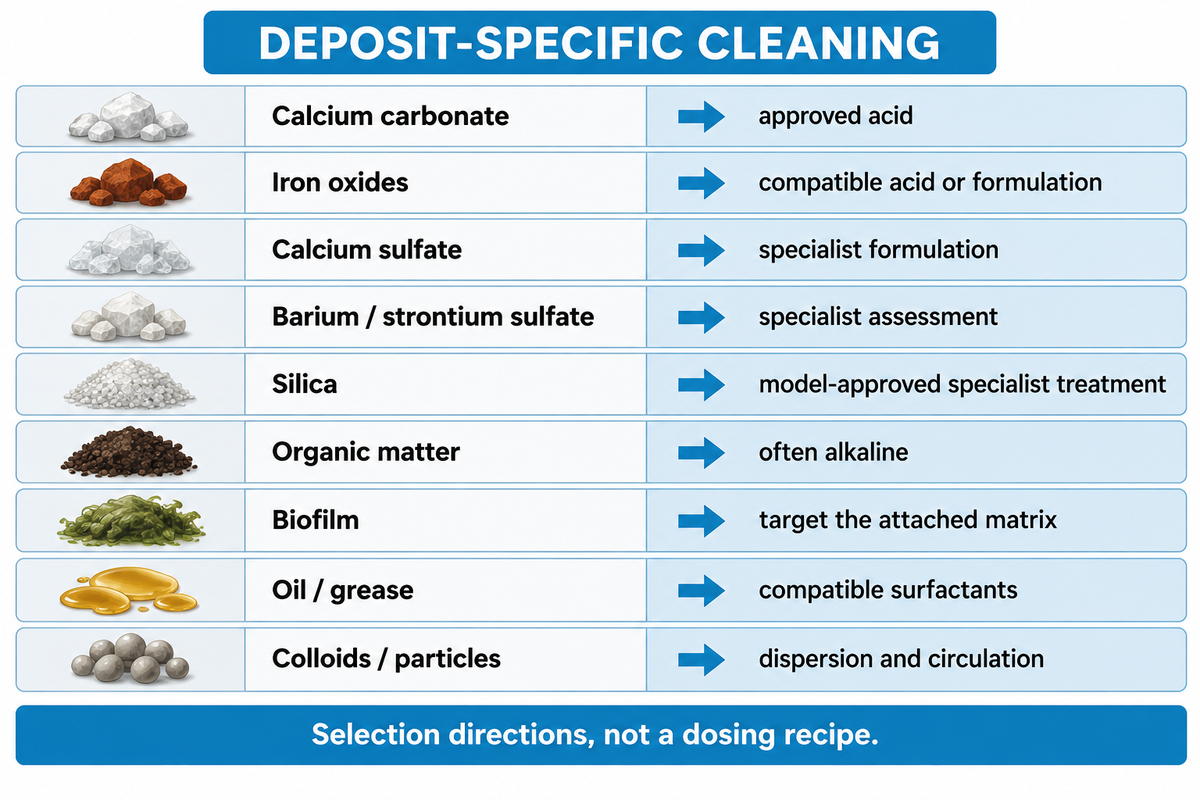
An acidic cleaner is commonly used for carbonate scale and selected metal deposits; alkaline cleaners address organic fouling, including biological matter. High and low pH cleaning target different deposits. An approved acid product can dissolve carbonate scale, and a different assessment is needed for refractory sulfate deposits. Mixed fouling may need sequential treatments.
What chemicals are commonly used to clean RO membranes?
Common options include citric acid, mineral acids, sodium hydroxide (NaOH), chelating agents and formulated products containing surfactants or dispersants. The cleaner should work for both the foulant and membrane. Weak acids also need checks; stronger formulations can damage an incompatible membrane. Concentration, pH, temperature and contact time work together.
| Deposit | Cleaning direction | Limit that changes the decision |
|---|---|---|
| Calcium carbonate | Approved acidic cleaner | Confirm carbonate scale rather than another calcium salt |
| Iron oxides | Compatible acid or formulated metal cleaner | Mixed organic deposits can change the sequence |
| Calcium sulfate | Specialist formulation, often involving chelation | Do not assume the carbonate-scale treatment will work |
| Barium or strontium sulfate | Specialist assessment | Highly insoluble deposits can resist cleaning |
| Silica | Model-approved specialist treatment | Polymerized deposits can be difficult to remove |
| Organic matter | Often an alkaline formulation | Mineral-organic complexes can require a different sequence |
| Biofilm | Compatible formulation targeting the attached matrix | Microorganism inactivation alone does not remove the deposit |
| Oil or grease | Compatible surfactant-containing formulation | Acid-first treatment can make some deposits harder to clean |
| Colloids or particles | Compatible dispersion plus adequate circulation | Correct upstream filtration to prevent recurrence |
The summary of selection directions cites FilmTec and Hydranautics, with the composite-deposit exception below. DuPont advises against using sulfuric acid as a cleaning agent, because calcium sulfate can precipitate. Cleaning solutions also need suitable make-up water; raw water can contain another impurity or a precipitating salt.
FilmTec recommends alkaline-first cleaning for its mixed organic, colloidal or biological fouling cases. Tightening of organic deposits by acidic treatment has been reported. But An and colleagues’ 2025 study found citric-acid-first treatment more effective for its tested humic-acid/inorganic-salt mixture. The authors attributed this to the removal of mineral deposits in a composite layer, and therefore, this explains the exception given above. This, however, doesn’t give the right to modify the procedure of an already installed element.
Illustrative procurement scenario: A maintenance team has citric acid in stock and has a layer of slime in the lead stage. Not buying additional chemical looks attractive, but the deposit may contain biological or organic foulants and mineral scale. The technician compares the feed history and deposit analysis with the chemical supplier’s cleaning trial. If the formulation loosens attached foulants and biofilms, but the loop can’t carry them out, then the problem is partly hydraulic. If the trial supports a different sequence, the membrane supplier must still verify compatibility. The team may clean the membrane with matched formulation and circulation conditions.
For recurring fouling, review the industrial RO pretreatment upstream of the membrane. A chemical clean cannot compensate indefinitely for failed pre-filters or untreated feed contamination.
Membrane Limits: Check pH, Temperature and Exposure Together
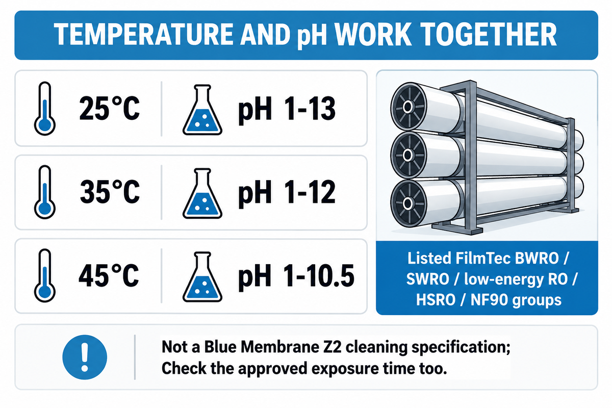
The permitted cleaning pH range may narrow with increasing temperature. Consider the combination, not the separate maximum values copied from a datasheet. The duration of exposure and the history of cleaning are also important. A membrane rated for a particular operating temperature is not automatically approved for every cleaner at that temperature.
| Maximum cleaning temperature | Listed pH range | Application boundary |
|---|---|---|
| 25°C | 1–13 | Listed FilmTec groups only |
| 35°C | 1–12 | Use the full approved procedure and exposure limits |
| 45°C | 1–10.5 | Not a Blue Membrane Z2 cleaning specification |
These limits show that heating an alkaline solution may alter its acceptance. They aren’t transferable to another brand or every nanofiltration model. In a 2015 RO cleaning study, changes in permeability and separation did not behave identically; reversing a permeability change did not necessarily reverse changes in rejection.
For Blue Membrane fouling-resistant RO membrane elements, obtain the approved cleaning window through batch identification and the installed model. Include the cleaner, pH, concentration, temperature and maximum exposure time in the procedure. A fouling-resistant designation does not make the membrane immune to incompatible chemistry or establish a guaranteed cleaning interval.
RO System Cleaning Procedure: Flush, Circulate, Soak and Rinse
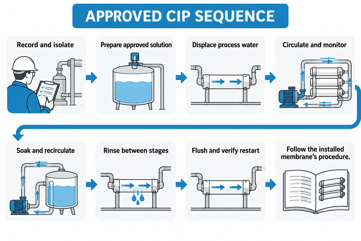
A clean-in-place loop circulates a compatible solution through the elements to loosen deposits, followed by rinsing before production resumes. Preparation involves displacing and then circulating the solution at low pressure. Soaking is controlled and rinsing is performed. Time, flow and temperature are controlled in accordance with the installed membrane’s procedure. A step-by-step guide can’t provide universal valve positions.
- Record and isolate. Save pre-clean readings, isolate the stage and protect the feed and product-water connections.
- Prepare the solution. Use approved chemicals and chlorine-free permeate or deionized make-up water; follow chemical-handling instructions.
- Displace process water. Introduce solution at the specified low pressure and initial flow; divert the displaced water as directed.
- Circulate and monitor. Maintain the approved flow direction, pH and temperature; replace exhausted or heavily contaminated solution.
- Soak and recirculate. Use the approved exposure limit and circulation sequence; keep the solution within its permitted conditions.
- Rinse between stages. Remove one cleaning solution before introducing an incompatible treatment.
- Flush and restart. Rinse with suitable clean water, divert initial permeate and verify quality before returning it to use.
Hydranautics TSB107.30 calls for stage-by-stage cleaning and a dedicated cleaning pump, rather than the production high-pressure pump. Adequate velocity carries the deposits away; excess pressure can force water through the membrane and cause other damage. Don’t assume that because the tank is clear, the job is done. Monitor the return solution.
The US EPA’s Membrane Filtration Guidance Manual, sections 7.2–7.3, explains cross-connection protection, rinsing to normal production-water conditions and the risk of damaging spiral-wound glue lines through permeate-side backpressure. The EPA cleaning guidance is also applicable to maintenance of cross-connection protection. Keep cleaning solution away from product being stored. This 2005 EPA Engineering Guidance isn’t a substitute for the manufacturer’s operating procedure.
| Constraint | What can go wrong | Preparation and owner |
|---|---|---|
| Pump and return pipe | Insufficient circulation leaves loosened deposits behind | Maintenance checks the required flow against the complete loop |
| Tank and solution volume | Vessels and piping consume the prepared batch | Maintenance includes loop hold-up and displacement losses |
| Heating and monitoring | Solution leaves the permitted pH–temperature window | Operator checks calibrated temperature and pH instruments |
| Stage isolation | Contamination moves into another stage or product water | Maintenance verifies the isolation arrangement |
| Permeate return | Backpressure damages the element | Maintenance follows the approved open-return arrangement |
| Waste handling | Spent solution cannot be discharged as planned | Site environmental staff arrange collection and disposal |
| Rinse and restart water | Production starts while cleaner remains | Quality staff confirm the prescribed rinse and water-quality endpoints |
If the use of acid prior to high pH cleaning is approved, rinse the acid out before changing solutions. Maintain a cleaning log that includes chemical identity and concentration, initial and final pH, temperatures, circulation flow, exposure time and observations. The log should also contain the identity of the fresh water used for rinsing, and the disposition of the spent solution. The log helps distinguish an ineffective substance from a pump, valve or temperature-control failure.
Clean Again or Replace? Compare Three Performance Changes
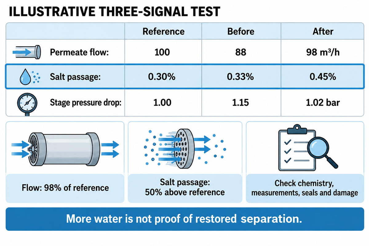
Normalized flow, salt passage and pressure drop should be compared after rinsing and stabilization with the same reference used before cleaning. If the normalized flow after cleaning is improved, but salt passage is worse, this is a fault signal and not a successful clean. Then consider the product-water requirements for the intended use, and be aware of the rate of fouling.
Three-Signal Recovery Test
In the case where rinsing and stabilization have been accomplished, this comparison of the three signals with their reference values is made to select the next diagnostic action. Enter the reference, pre-clean and stabilized post-clean measured values side by side. This is a troubleshooting guide, and not a validation of drinking water, or a replacement for tests required by the process.
| Normalized reading | Reference | Before | After |
|---|---|---|---|
| Permeate flow | 100 m³/h | 88 m³/h | 98 m³/h |
| Salt passage | 0.30% | 0.33% | 0.45% |
| Stage pressure drop | 1.00 bar | 1.15 bar | 1.02 bar |
In this case, flow is at 98% of reference and pressure drop is approximately at its starting value. However, salt passage is at 50% above the reference (0.45-0.30) ÷ 0.30 × 100. Check remaining chemistry, measurements, seals and membrane damage before releasing product water. Ordering a stronger repeat clean may make the damage worse.
“When the membrane surface is oxidized, the salt rejection decreases and the permeate flow rate increases.”
| Observed pattern | Next action | What it does not prove |
|---|---|---|
| Actual flow falls as feed cools | Normalize the readings | Fouling has not yet been established |
| Normalized flow remains low | Check chemistry, circulation and deposit identification | A stronger chemical is not automatically needed |
| Flow and pressure drop both recover poorly | Review deposit removal and stage-specific conditions | One failed clean does not automatically require replacement |
| Pressure drop stays high | Investigate feed-channel restriction and circulation | Normal product quality does not rule out blockage |
| Salt passage rises without a major flow change | Check measurements and seals; investigate leakage | It does not identify membrane oxidation by itself |
| Flow improves while salt passage worsens | Investigate damage, leakage and residual chemistry | More water is not proof of restored separation |
| Recovery fades quickly | Review residual biofilm, feed changes and pretreatment | Startup recovery does not establish lasting control |
| Three readings improve but a required water test fails | Keep water out of the intended process and diagnose the failure | Salt passage cannot represent every contaminant |
| Readings and required quality tests meet operating criteria | Resume the approved operating plan and trend subsequent performance | Future fouling or fixed remaining life is not guaranteed |
A repeated-cleaning study conducted in 2021 in membrane fouling simulators showed declining pressure-drop restoration in successive cycles and residual biomass accumulation. Record the operating time until another cleaning trigger, alongside the immediate recovery. Note whether repeated cleaning supports membrane longevity or provides transient improvement. For persistent poor separation or physical damage, use the RO membrane replacement guide after diagnosing the cause.
Quality staff also need tests that are related to the water’s end use. Research on neutral organic compounds shows their rejection is structure dependent. Thus, one can’t rely on salt rejection to conclusively determine the removal of the target organic substance in a water reuse process.
Cleaning Cost: Chemicals, Downtime and Off-Site Service

One off-site service provider publicly listed cleaning at US$167.72/4″ element and US$270.39/8″ element in October 2026. These are Big Brand Water’s listed prices, not an industry average. Compare the service charge to the cost of removing, shipping, reinstating the equipment and the loss of production.
Cleaning cost example
Example inputs: six 8-inch elements sent to the service for US$270.39 per element. The seller lists pre- and post-cleaning tests and an optional preservative charge of US$30 per element. The order quantity of six is for illustrative purposes. This isn’t a Blue Membrane quotation.
| Item | Calculation or treatment | Amount |
|---|---|---|
| Cleaning service | 6 × US$270.39 | US$1,622.34 |
| Optional preservative | 6 × US$30 | US$180.00 |
| Subtotal with that option | US$1,622.34 + US$180.00 | US$1,802.34 |
| Freight and handling | Confirm quotation inclusions and both transport legs | Add the applicable charge |
| Removal and reinstatement | Use the site’s labor and handling estimate | Add the applicable charge |
| Production cover | Use backup-water cost or the chosen lost-production measure | Avoid counting the same loss twice |
The calculated US $1,802.34 is a service-plus-preservative subtotal, not the delivered cost of restoring the plant. Finance should consider the alternatives for the same outage window. A spare set can change the downtime window calculation; an on-site CIP can eliminate the shipping cost, but requires suitable equipment, trained personnel and a means to handle the waste.
Clean in place
- Keep elements installed.
- Provide a suitable cleaning loop and waste route.
- Budget the site outage and restart testing.
Off-site cleaning
- Remove, preserve and transport elements as instructed.
- Specify element testing and the service scope.
- Budget transit, reinstatement and production cover.
Cleaning Suppliers and Services: Match the Job to the Provider

Purchase cleaning chemicals, diagnostics and offsite cleaning as separate services. Avista offers lab analysis, membrane autopsy and OSCAR offsite cleaning. PWT offers liquid Lavasol and powder OptiClean cleaners. Big Brand Water offers element cleaning services and testing. A product catalogue by itself isn’t sufficient to ensure product compatibility with the elements installed on site.
When requesting industrial water treatment services, provide element models, quantities, feed analysis, normalized performance trend and previous cleaning logs. Ask the provider to state chemical compatibility, test conditions, handling instructions, turnaround and what happens if an element fails its post-clean test. Procurement can then compare the same job rather than three different scopes.
Blue Membrane manufactures membrane elements and integrated water treatment systems. For an element inquiry, state the model, the feed conditions and the performance issue.
Water Treatment Outlook: Recovery Must Preserve Rejection
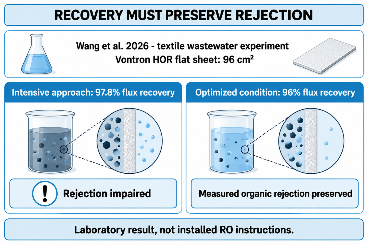
New cleaning methods should be able to preserve and restore separation as well as recovery. This is of particular importance when dealing with wastewater reuse, as an increase in flow doesn’t necessarily mean the required contaminants are being removed. The best approach is to compare recovery, water quality and fouling, all under the same operating conditions.
The study of textile wastewater treatment in January 2026 used a 96 cm² Vontron HOR flat sheet (membrane). An intensive combined cleaning and backwashing approach recovered 97.8% of the initial specific flux but impaired rejection. However, this negatively affected rejection. An optimized condition recovered 96% while preserving the measured organic-rejection performance in that experiment. The results illustrate that the highest recovery percentage can’t always be justified.
The experimental flat sheet isn’t a commercial spiral-wound Blue Membrane element. Its reverse-flow settings are not operating instructions for an installed RO train. The useful lesson for the water treatment industry is to test a new procedure against throughput and separation, then watch the operating period that follows. Maintain the analyses of product water for the duration of the test.
Discuss the element and operating conditions
Share the installed model, feed-water analysis and before-and-after performance readings with Blue Membrane. For replacement or a fouling-resistant element enquiry, those details help define the required flow, separation and feed conditions.
RO Membrane Cleaning FAQ
Is RO membrane cleaning safe?
Industrial cleaning requires a compatible procedure and trained operators.
Check the installed element’s permitted combination of chemical concentration, pH, temperature and exposure time before starting. Isolate the system and protect product-water connections. Follow the chemical safety data and equipment instructions for handling, protective equipment and waste disposal. Complete the prescribed rinse and water-quality checks before returning the system to production; a general online recipe cannot establish those conditions.
Can I use bleach instead of an RO membrane cleaner?
Do not substitute bleach for an approved cleaner for conventional polyamide elements.
Chlorine and other incompatible oxidants can damage the separation layer, and washing cannot repair that damage. Instructions for disinfecting an empty household filter housing address a different operation. Remove or protect components exactly as the equipment procedure requires. Use only a treatment expressly approved for the installed membrane, with its specified concentration, temperature and contact time.
What is the effective concentration of citric acid in cleaning an RO membrane?
Use the concentration specified for the identified deposit and installed membrane.
Citric acid can be useful for selected mineral deposits, but the percentage alone does not define a safe or effective procedure. Solution pH, temperature, exposure time and the other materials in a mixed deposit also matter. It is not a universal remedy for silica or biofilm. Monitor the cleaning solution and follow the approved formulation rather than increasing concentration to compensate for poor circulation.
Which chemical is used as RO antiscalant?
RO antiscalants are formulated products selected for the feed chemistry.
They help prevent precipitation during operation. They do not replace a cleaning solution for established deposits. Select the product and dose against the expected scaling conditions.
Do I need to remove the RO membrane and filters?
Industrial CIP normally cleans installed elements; off-site service requires removal.
A domestic system may instead require removing the membrane and cartridges before sanitizing the housing and storage tank. Follow that model’s instructions; do not adapt an industrial chemical procedure to a household unit. Before opening an industrial pressure vessel, isolate and depressurize the equipment and follow the element-handling procedure. For off-site service, agree on packaging and preservation before shipping so storage conditions do not create another problem during the cleaning outage.
How often do you have to change the RO membrane?
Replacement follows diagnosed condition and usable performance, not one universal age.
Persistent poor separation, physical damage or uneconomic production may justify replacement. Correct the underlying feed or operating problem before installing new elements.
Why is RO membrane cleaning not working?
The chemistry, circulation or diagnosis may be wrong, or the element may be damaged.
Check the cleaning log for solution pH and temperature drift, inadequate return flow and exhaustion of the cleaner. Reconsider the identified deposit, especially mixed fouling. Also rule out cold feedwater, restricted prefilters, low pressure, instrument error and leaks. Compare stabilized performance with the original reference before deciding on another treatment. If recovery fades rapidly, investigate residual biomass and pretreatment instead of assuming each shorter operating run needs a stronger chemical.
Related Articles
- Fouling-resistant RO elements element selection and application
- 4040 and 8040 membrane housings equipment fit
- Brackish-water RO operating cost the wider production budget
- RO membrane salt rejection interpreting separation performance
References & Sources
- ASTM D4516-19a: Standardizing Reverse Osmosis Performance Data public scope and significance
- Membrane Filtration Guidance Manual US EPA, November 2005
- Temperature-dependent performance of cleaning sequences An et al., 2025; author abstract indexed by AGRIS
- Periodic chemical cleaning and biofilm removal Sanawar et al., Water Research X, 2021
- Textile-wastewater membrane cleaning experiment Wang et al., Membranes, 2026
- Chemical cleaning effects on RO properties and separation Tu, Chivas and Nghiem, 2015
- Neutral organic contaminant rejection Breitner, Howe and Minakata, 2019
- Operational warning signs and membrane cleaning Summerfield, 2003
About this cleaning guide
Cherry prepared this guide for Blue Membrane to explain RO cleaning choices and post-clean performance checks. Manufacturer instructions and published research provide the technical basis; the operating scenarios are illustrative. The cost calculation uses a named seller’s listing checked in October 2026. Neither those examples nor the cited laboratory results describe Blue Membrane customer trials or guarantee membrane recovery.